


5
Tank installation
Logano G334X – 6 720 811 237 (2014/05)
18
Total air supply from outside the building
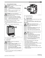
Make sure that the boiler room has two permanent air vents, one of
which must not be more than 12 inches (300 mm) from the ceiling and
the other not more than 12 inches (300 mm) from the floor of the boiler
room, measured from the outer edge of the opening. The openings must
be connected either directly or via air ducts to the outside or to rooms
that have an unobstructed connection to the open air (crawl space or
attic). The smallest dimension of all air intake and outlet openings must
be not less than 3 inches (80 mm).
• If there is a direct connection to the outside, each opening must have
a minimum cross-section of one square inch (25 mm
2
) per
4000 Btu/h (550 mm
2
/kW) of the total combustion output of all gas-
fired appliances inside the closed room.
• If there is a connection to the outside through a ventilated attic with
vertical ventilation ducts, each vent aperture must have a minimum
cross-section of one square inch per 4000 Btu/h (550 mm
2
/kW) of
the total burner output of all gas-fired appliances inside the closed
room.
• If there is a connection to the outside through a ventilated attic with
vertical ventilation ducts, each vent aperture must have a minimum
cross-section of one square inch per 2000 Btu/h (1100 mm
2
/kW) of
the total burner output of all gas-fired appliances inside the closed
room.
• If the openings are connected to ventilation ducts, the ducts must
have the same cross-section area as the openings to which they
connected.
5.10.2 Requirements for connection to chimneys or flue gas
systems
The flue connector must comply with the regulations of the National Fuel
Gas Code NFPA 54, Part 7, Venting of Equipment, and the local building
codes. In Canada the regulations of CAN/CSA B 149.1 as well as local
building codes apply.
Flue connections of heating systems with natural venting must not be
connected with any component of a mechanically operated flue gas
system that operates with positive pressure.
The cross-section of the flue connector must not be less than that
specified in Tab. 11.
If the boiler will be connected to a brick chimney, the chimney must be
thoroughly inspected before use. The chimney must be clean, in
compliance with construction codes and of sufficient dimensions.
Chimneys with an internal liner are preferred and are permitted only if
the liner complies with all national, state and local construction codes.
Liners of fire-glazed brick with moisture-proof joints and liners of
corrosion-resistant material are recommended.
Contact the local gas supply utility for advice and recommendations for
flue connection and chimney liners. A flue pipe of single-walled sheet
metal is required for flue connections for type II models.
An adequate chimney height in compliance with the tables of the
National Fuel Gas Code, ANSI Z 223.1, is required.
Disconnecting a boiler from a common flue gas system
If an existing boiler is disconnected from a common flue gas system, the
flue gas system is now oversized. Proper venting for the remaining
heating systems is then no longer guaranteed.
Procedure for checking the flue gas system:
Carry out these steps with every heating system that remains connected
to the flue gas system when the boiler is disconnected from a flue
header. Operate the heating system that is to be disconnected from the
flue header, while the other heating systems connected to the flue gas
system remain off.
In Canada the regulations in accordance with CAN/CSA B 149.1 and 2
Installation Codes apply.
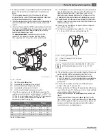
Boiler size
Diameter of the flue gas connector
[inch]
[mm]
73
8
203
92
9
229
116
10
254
132
10
254
Table 11 Cross-section of the flue connector
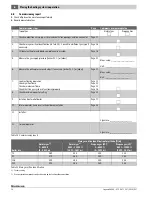
A
Seal all unused openings of the common flue gas system.
B
Perform a visual inspection of the flue gas system to ensure that
it has the correct dimensions and longitudinal inclination. Make
sure that the system is not blocked, leaking, corroded or has
any other faults that cause it to operate improperly.
C
If necessary, close all doors and windows of the building. Also
close all doors leading to other rooms of the building at the
location where the heating systems still connected to the flue
gas system are located. Switch off dryers and all appliances that
are not connected to the flue gas system. Operate all venting
fans and bathroom exhaust fans at their highest speed. Fans in
use in summer must remain in operation and oven exhaust
system flaps must be closed.
D
Start up the heating system to be tested. Follow the instructions
for commissioning. Set the thermostat for continuous
operation.
E
After the main gas burner has been operating for five minutes,
check the opening at the flue gas collector for drafts with an
open flame, or with the smoke of a cigarette, cigar or pipe.
F
Perform this check on all heating systems that remain
connected to the flue gas system to ensure that the flue gases
are vented properly. Then place all doors, windows, venting
fans, exhaust system flaps, and all other gas-fired appliances
back into their original state.
G
Any incorrect condition of the common flue gas system must be
corrected to ensure that the heating system complies with the
regulations of the National Fuel Gas Code, ANSI Z 223.1. If the
size of any component of the common flue gas system is
changed, the complete flue gas system must be resized to
comply with the relevant tables in Part 11 of the National Fuel
Gas Code, ANSI Z 223.1.
Table 12
Summary of Contents for G334X
Page 38: ...10 Logano G334X 6 720 811 237 2014 05 38 Notes ...
Page 39: ...10 Logano G334X 6 720 811 237 2014 05 39 Notes ...
Page 40: ......


