


5
Tank installation
Logano G334X – 6 720 811 237 (2014/05)
13
Power connection and connections of additional components
▶ Establish a permanent connection to the main power connection in
accordance with the locally applicable regulations.
▶ Route all cables to the controller through the conduit and connect in
accordance with the controller's wiring diagram.
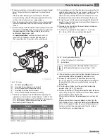
Fig. 15 Front of boiler
[1]
Measuring point (immersion well)
[2]
Quadrant (blanking piece)
[3]
Boiler water sensor (Logamatic 2107 control)
Installing strain relief
▶ Secure all cable runs with cable clips (included with the controller).
▶ Insert wiring clip with wiring from above into the slot of the clip
frame; the lever bar must point upwards (step 1).
▶ Slide the cable ties downwards (step 2).
▶ Push against the clips (step 3).
▶ Flip the lever up (step 4).
Fig. 16 Secure wiring with wiring clip
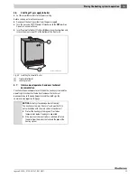
Installing jacket panels
▶ Swivel display unit to the desired position.
Fig. 17 Swivel display unit
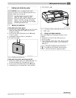
▶ Position terminal cover and screw to control.
Fig. 18 Positioning the terminal cover
[1]
Controller
[2]
Terminal cover
WARNING:
Fire hazard from hot boiler components!
Hot boiler components may damage electrical cables:
▶ Make sure that all cables are routed through the
conduit provided or along the boiler's thermal
insulation.
6 720 810 547-09.1T
1
2
3
1
6 720 615 362-20.1SL
For combinations with L storage tanks, we recommend
positioning the display unit straight.
6 720 808 510-06.1T
1
2
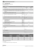
Summary of Contents for G334X
Page 38: ...10 Logano G334X 6 720 811 237 2014 05 38 Notes ...
Page 39: ...10 Logano G334X 6 720 811 237 2014 05 39 Notes ...
Page 40: ......


