


5
Tank installation
Logano G334X – 6 720 811 237 (2014/05)
12
Connecting the power supply
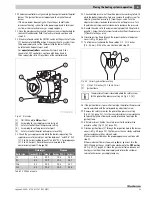
▶ Establish a permanent connection to the factory-installed aquastat in
accordance with the locally applicable regulations.
▶ Mount an ON/OFF switch near the boiler.
Fig. 12 Main power switch (by customer)
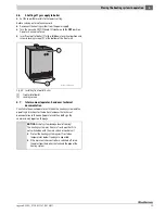
5.6
Installation of Logamatic 2107 control
(optional accessories)
The boiler is fully functional with the factory-installed aquastat.
A Logamatic 2107 controller can be installed in addition to the factory-
installed aquastat.
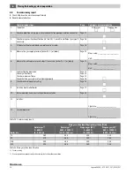
▶ Insert tabs (
Fig. 13 [2]) on the controller into the oval holes [3].
▶ Slide the controller forward.
▶ Press the flexible hooks [1] into the knock-outs provided until they
snap Into place.
Fig. 13 Installing the controller
[1]
Flexible hooks
[2]
Tabs
[3]
Oval holes
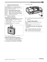
▶ Unscrew the screws from the top cover [1].
▶ Remove the top cover from the controller.
▶ Secure the control panel with self-tapping screws [2].
Fig. 14 Removing the top cover
[1]
Top cover screws
[2]
Self-tapping screws
Installing the boiler water sensor
▶ Route boiler water capillary package wiring under the front boiler
cover to the measuring point (sensor well).
▶ Remove dummy from the sensor well.
▶ Insert the boiler water sensor into the sensor well all the way in place
of the dummy.
▶ Press sensor clip (standard delivery of controller) from the side or
from above onto the head of the sensor well.
▶ Carefully roll up unnecessary wiring and capillaries and stow in the
Logamatic 2107 control.
Note the following when making electrical connections:
▶ Carefully route the cables/leads and capillaries.
▶ Do not kink the capillaries.
▶ Electrical work inside the heating system may be
carried out only by a licensed electrician.
▶ Observe the local regulations.
7 747 010 720-
8
0.1RS
ON
OFF
Summary of Contents for G334X
Page 38: ...10 Logano G334X 6 720 811 237 2014 05 38 Notes ...
Page 39: ...10 Logano G334X 6 720 811 237 2014 05 39 Notes ...
Page 40: ......


