


®
750 Control Panel Operation and Troubleshooting
10
463-3000-08 revised Sept 16, 2013
changed on any of the four pages by selecting the page to be changed and then entering
Adjust Mode.
In
Adjust Mode
a new button bar is displayed identifying the button functions. Button 1
corresponds to
the upper left gauge, button 2
to the upper right gauge, button 3
to the bottom left gauge and
button 4
to the bottom right gauge. Successive presses of the buttons selects a different parameter for
the gauge.
Adjust Mode
is exited by pressing button 5
and storing the new configuration even when
power is removed.
Note:
A gauge selection can only appear once per page. To move a gauge selection, the
existing gauge location must be changed first. Gauge selections are limited to the data currently being
received. Gauge pages can be configured in Demo mode to select any supported parameter. See
Data
Parameters Monitored
for a complete list of available parameters.
Adjust Mode
can be disabled in the
Configuration Menu
to prevent accidental changes.
Digital Gauge Pages
Digital Gauge Pages
display the same data as the Analog Gauge Pages but in digital only format. To enable Digital
Gauge Pages, press any of the first 4 buttons to show the top level button bar and then press button 2
. Alternate
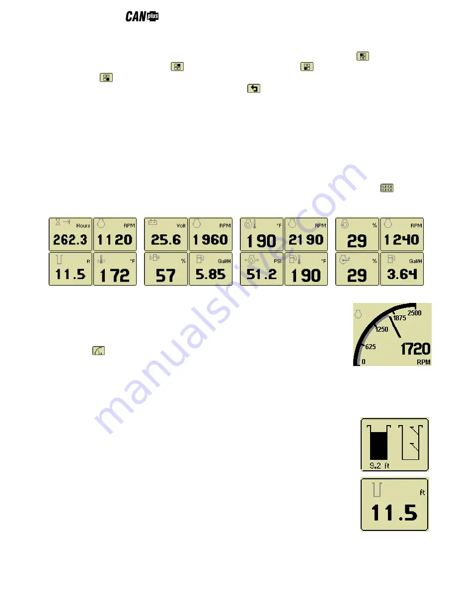
pages are selected by repeated pressing of button 2. The four standard gauge pages are shown below.
Page 1
Page 2
Page 3
Page 4
Note:
The 16 gauges are the same for Analog and Digital Gauge Pages. Adjustments in either Analog Gauge
Pages or Digital Gauge Pages affect the same gauge in the other mode.
Single Analog Gauge
Single Analog Gauge
uses the entire display for a single large analog gauge. This mode is
enabled by pressing any of the first 4 buttons to show the top level button bar and then
press button 3
. The gauge displayed is selectable by repeatedly pressing button 3 while
in the Single Analog Gauge mode while the menu bar is visible. The currently displayed
gauge is stored when power is removed (see
Preferred Screen Store
).
Note:
Gauge selections are limited to the data currently being received. See
Data Parameters Monitored
for a
complete list of available parameters.
Analog Transducer/Switch Gauge
The
Analog Transducer/Switch Gauge
displays the transducer value and the switch input
states. The left column represents the values as a bar graph with a digital value displayed
below. The right column shows whether the switches are ‘open’ represented by the pointer
being down or ‘closed’ represented by the pointer being up.
Digital Transducer Gauge
The
Digital Transducer Gauge
displays the transducer value as a digital only value. The switch
state is not displayed on the Digital Transducer Gauge.
Active Alarms
A flashing popup window is overlaid on the current screen when an active alarm is received.