41
6
System Start-up
(continued)
SCH Collectors Installation & Operation Manual
Clamp ring screw connections
■
Cut the copper pipe to length and deburr.
■
First, slide the clamp ring nut over the pipe, then clamp the
ring itself.
■
Insert the prepared pipe into the screw connection until its
stop is reached.
■
Tighten clamp ring nut by hand.
■
Use open-ended wrench to tighten clamp ring screw
connection (approximately 33 ft. lb.), retighten if necessary.
■
When tightening the clamp ring screw connection, use two
wrenches–using one wrench to prevent the pumping station
from turning.
■
Close the fill/flush valve (forward flow) and switch off the
filling and flushing pump.
■
Open return ball valve (by turning the blue thermometer
handle 90° counter-clockwise until it stops).
■
The solar system features an air separator. Open the
bleeder valve until the solar liquid exits free of air bubbles.
■
Only if collector bleeder is installed: Bleed the system on
the collector until the solar liquid exits free of bubbles.
■
If necessary, increase the test pressure again to 60
psi and check the system for leaks. If the pressure gauge
shows the pressure dropping substantially, you have a leak
in the system.
■
Set the operating pressure to 60 psi as prescribed by the
system
manufacturer.
■
Start up the circulation pump at maximum speed and
allow liquid to circulate for at least 15 min.
■
Remove the filling station hoses and screw the caps on the
flushing and filling valves.
■
Check the system again for leaks. Use the red and blue
thermometer handles to fully open the forward flow and
return ball valves.
■
Activate speed control on solar control unit. The highest
speed level should be set on the pump (phase control).
Note
:
The minimum speed set on the solar control unit must
not fall below the pump’s minimum nominal speed. Note
instructions for pump and solar control unit.
■
Once the installation settings have been completed and
checked, fit the solar station’s front insulation shell.
■
Refer to the collector manufacturer’s recommendations for
minimum flow requirements.
Flat seal screw connections
■
All pre-fitted solar station screw connections are firmly
tightened in the factory so that they do not need to be
retightened.
Torque levels when tightening flat seal screw connections
using AFM 34 flat seals, s = 2mm.
– 3/4" screw connection 26 Ft. lb
– 1" screw connection 40 Ft. lb
– 1 1/4" screw connection 66 Ft. lb
– 1 1/2" screw connection 96 Ft. lb
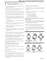
Operation, multi-function ball valve and
check valve
■
The forward flow ball valve must be open for filling, flushing
and bleeding solar systems with a filling and flushing pump.
The return ball valve should be closed.
■
Both flow checks should be opened in order to bleed the
solar system (thermometer handles in 45° position).
■
The two mult-function ball valves must be fully open in
order to bleed the solar system (turn the red and blue
thermometer handles counter-clockwise until the stop is
reached).
Figure 6-1 Forward flow multi-functioning instruments
SETTING FOR OPERATIONS,
FILLING, FLUSHING, DRAINING
FLOW CHECK CLOSED
BALL VALVE OPEN
DRAINING
FLOW CHECK OPEN
BALL VALVE 1/2 OPEN
SERVICE
BALL VALVE
CLOSED
Figure 6-2 Return multi-functioning instruments
SETTING FOR OPERATIONS
FLOW CHECK CLOSED
BALL VALVE OPEN
DRAINING
FLOW CHECK OPEN
BALL VALVE 1/2 OPEN
SERVICE, FILLING FLUSHING
BALL VALVE CLOSED

