SCH Collectors Installation & Operation Manual
34
Installation & Operation Manual
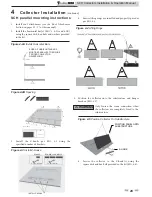
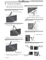
Figure 4-31 Install Mechanical Connection Kit
BEND TABS DOWN
18. Reinstall the collector railing removed in Step 17
(FIG.
4-32).
Figure 4-32 Reinstall Collector Railing
REINSTALL COLLECTOR RAILING
OPTIONAL MECHANICAL
CONNECTION KIT
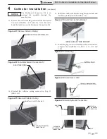
19. Install the side by side bracket using the square disks and
hex bolts provided in the kit (FIG. 4-33).
Figure 4-33 Install Side by Side Bracket
INSTALL SIDE BY SIDE BRACKET
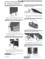
17. Remove the collector railing and install the Mechanical
Connection Kit (FIG.’s 4-30 and 4-31). Note: Be sure to
bend the tabs down on the Mechanical Connection Kit.
Figure 4-30 Remove Collector Railing
REMOVE COLLECTOR RAILING
4
Collector Installation
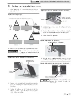
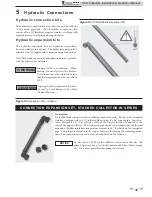
Figure 4-34 Install Plug
INSTALL PLUG
Figure 4-35 Install Sensor Well
Figure 4-36 Install Hydraulic Connections
20. Install the plug, sensor well and hydraulic connections to
complete the installation (see FIG.’s 4-34, 4-35 and
4-36).
SENSOR
WELL
EXPANSION
SET (HYDRAULIC
CONNECTION)
PLUG
EXPANSION
SET (HYDRAULIC
CONNECTION)

