background image

11

7  

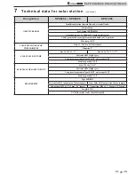
Technical data for solar station  

(continued)

Designation

SPS0250 / SPS0500

SPS1000

GRAVITY BRAKES

Installation location: forward flow and return ball valves

Material: Brass

Seal: O-ring 70 EPDM 291

Opening pressure: 2 x 200 mm WS (using metal spring)

Can be positioned by moving thermometer handle to 45

°

F position

Max temp 356

°

F

SOLAR DIAL INDICATOR 

THERMOMETER

Scale: 32 - 288

°

F in 3.6 F increments

Diameter: 2"

FLAT SEALS FOR PUMP

Size: 30 x 22 x 2 - 1"

Size: 44.5 x 33 x 2 - 1 1/2"

Material: AFM 34 light grey

Long-term temperature: Liquid 482

°

F, water vapor 360

°

F

Peak temp. briefly: 720

°

F

FLAT SEAL FOR SAFETY GROUP

Size: 17 x 24 x 2 - 3/4"

Material: AFM 34 light grey

Long-term temperature: Liquid 482

°

F, water vapor 392

°

F

Peak temp. briefly: 752

°

F

BLEEDER PIPE

Type SER-RDT

Series: Solar 8010 compression 22 mm compres.

Series: Solar 8010 compression 28 mm compres.

Connection: M28 x 1.5 / 22 mm / 3/8" female

Connection: M36 x 1.5 / 28 mm / 3/8" female

Length: 9.25 ft

3/8" bleeder valve can be shut off manually


SL-PS Installation & Operation Manual

Summary of Contents for TISUN PS1000

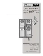
Page 1: ...only be used by a qualified heating installer service technician Read all instructions before installing Perform steps in the order given Failure to comply could result in severe personal injury death...

Page 2: ...to personal injury or property damage HAZARD DEFINITIONS 2 1 GENERAL INFORMATION Included components 3 4 2 INSTALLING THE SOLAR STATION Installing the solar station on a wall 5 Installing the relief v...

Page 3: ...operation The provisions stated in DIN EN 12976 1 should be observed when installing solar systems The expansion tank should be regularly checked according to DIN 4807 Solar systems should be grounde...

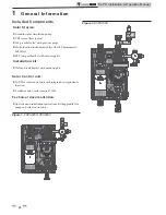
Page 4: ...with mounting kit Installation kit Wall and tank bracket with mounting kit 1 General Information Solar Control unit LCD Plus solar control unit with integrated energy balance function 2 collector and...

Page 5: ...ion should be noted The safety valve must be easily accessible No valves should be placed between relief valve and pump station The relief valve should be piped to a suitable drain as close as possibl...

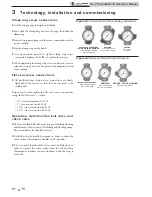
Page 6: ...tion 40 Ft lb 1 1 4 screw connection 66 Ft lb 1 1 2 screw connection 96 Ft lb Operation multi function ball valve and check valve The forward flow ball valve must be open for filling flushing and blee...

Page 7: ...erms of freeze protection Fill the solar system via the filling and flushing pump and then flush the solar circuit for at least 15 min to purge all of the air out of the circuit Close the fill flush v...

Page 8: ...4 0 4 5 5 0 5 5 6 0 6 5 7 0 7 5 8 0 Volumetric flow rate GPM Residual delivery height Ft Max residual delivery height pressure drop of components Solar group with Grundfos UP 25 120U pump and GF Sens...

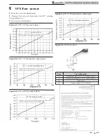
Page 9: ...Assignment of measurement range 32 212 F is equal to 0 5 3 5V Temperature rate calculation T 32 F U 0 5 V 3V 180 F Figure 6 4 VFS 2 40 temperature output signal VFS 2 40 output signal temperature Assi...

Page 10: ...size DN20 Measuringrange 26 3 17 GPM 5 10 5 GPM Measuring range 5 10 5 GPM Output signal Q 0 5 to 3 5 V proportional to GPM Output signal T 0 5 to 3 5 V proportional to 32 212 F Max pressure 145 psi...

Page 11: ...FLAT SEALS FOR PUMP Size 30 x 22 x 2 1 Size 44 5 x 33 x 2 1 1 2 Material AFM 34 light grey Long term temperature Liquid 482 F water vapor 360 F Peak temp briefly 720 F FLAT SEAL FOR SAFETY GROUP Size...

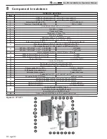
Page 12: ...0 UPS 25 99U 1 1 2 180 F12K09 115V 60Hz 13 Solar control unit LCD plus USA 115 Volt w SD card 14 SPS0250 Sensor direct 0 26 3 17 gpm w cable SPS0500 Sensor direct 0 50 10 5 gpm w cable 15 Power cord U...

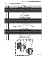
Page 13: ...16 Solar cross piece cpl USA w reducing pc and cap 17 Flow sensor housing 0 50 10 5 gpm w fill flush valve USA 18 Safety group KS0150 USA 19 Solar control unit LCD plus USA 115 Volt w SD card 20 UP 2...

Page 14: ...x 33 Ft lb When tightening the clamp ring screw connection use two wrenches one wrench to prevent the pumping station from turning Disassembling the solar station Wall bracket for repairs and service...

Page 15: ...atures and system pressures Allow pump to cool first Fully unscrew bleed screw and check ease of movement of pump rotor by turning the slotted shaft end with a screwdriver use force to turn if necessa...

Page 16: ...Revision Notes Revision A ECO C06520 initial release Revision B ECO C07610 reflects formatting adjustments SL PS I O Rev B 3 11...

Reviews: