LNS 326 S2 Startup Manual Download Page 5

4

START UP MANUAL

HYDROBAR EXPRESS 326 S2

End of bar setting :

Important : Before handling the barfeeder, stop the lathe at the end of part cycle.

1. Press the key 

[STOP]

.

2. Press the key 

[MENU]

.

The display reads : 

PARAMETERS RELATED

TO START UP

3. Press twice the key attributed to the icon 

[PAGE DOWN]

.

The display reads : 

SETTINGS FOR

POSITIONING

4. Press the key attributed to the icon 

[ENTER]

.

The display reads : 

POSITION OF THE END OF THE

BAR    **** MM

5. Press the key attributed to the icon 

[SET]

.

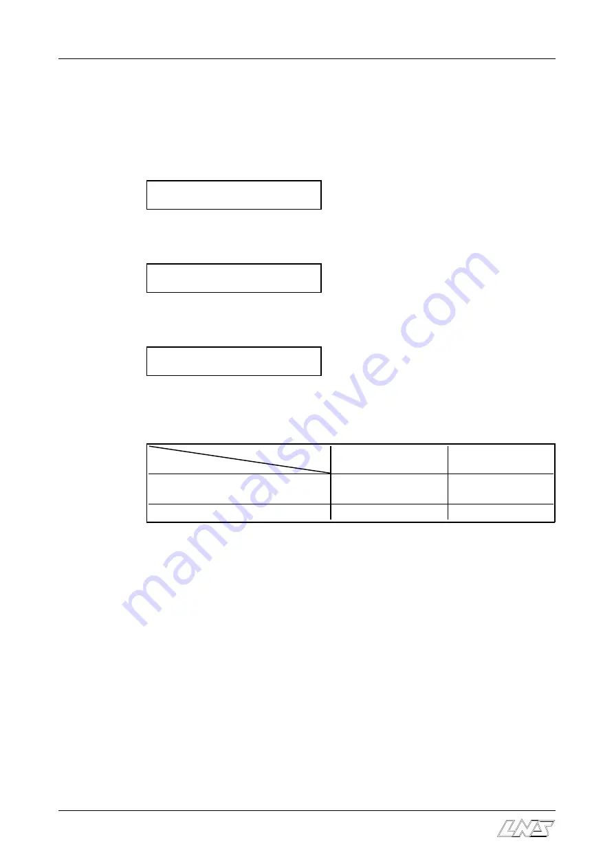
Depending on which sequence the bar feed is in when the parameter is selected, the
available functions and icons can change :

Functions

Conditions

By offset correction

By teaching

- Guiding channel closed
- No bar stock in the guiding channel

icon

 : [+/-]

icon : 

[TEACH IN]


- Guiding channel open

icon

 : [+/-]

---

[+/-]

 By offset correction

C

Press the key attributed to the icon 

[+/-]

.

The display reads the current end of bar position.

C

Enter the correction value with the numerical keys. Then, press the key attributed to
the icon 

[+]

 to add the value, or the  key attributed to the icon

 [-]

 to substract it. The

display reads the new end of bar position.

C

To exit the end of bar set mode,  press the key attributed to the icon  

[ESC].

[TEACH IN]


By teaching

C

Press the key attributed to the icon 

[TEACH IN]

.

The display reads the current end of bar position

C

Press the key 

[FWD]

 and advance the pusher to the desired position (see previous

page).

C

To  validate  the  new  end  of  bar  position, keep 

[ENTER]

  pressed  until  the  icon

disappears

.

6. To exit the set mode,  press the keys 

[MENU] 

or


[STOP]

.

Summary of Contents for 326 S2

Page 1: ...ENG...

Page 2: ...OPERATION 1 2 SETTINGS RELATED TO INSTALLATION 3 2 1 End of bar position 3 2 2 Top cut position 5 3 SETTINGS RELATED TO BAR STOCK AND MACHINED PARTS 7 3 1 Parameters 7 3 2 Mechanical settings 10 4 PU...

Page 3: ...ke a specific task are part of putting it into operation The device may be prepared for a different range of diameters by means of some very simple operations The process for putting the bar feed syst...

Page 4: ...ely5 mmor a 1 4 behind the chuck jaws or collet pads This will provide minimum bar stock remnant Regardless of the length of the bars or parts the end of bar position is always the same In very specia...

Page 5: ...ing Guiding channel closed No bar stock in the guiding channel icon icon TEACH IN Guiding channel open icon By offset correction C Press the key attributed to the icon The display reads the current en...

Page 6: ...ce With this system the setting is the same for any bar length The setting for the Top cut position may be adjusted at any time in one of two ways 1 Par correction de la valeur 2 Par apprentissage Tea...

Page 7: ...er the correction value with the numerical keys Then press the key attributed to the icon to add the value or the key attributed to the icon to substract it The display reads the new top cut position...

Page 8: ...the remote command displays the following text INPUT OVERALL PART LENGTH On the keypad enter 39 which represents the sum of the bar length and the thickness of the cutoff tool Press the ENTER key twi...

Page 9: ...LL PART LENGTH On the keypad enter 17 which represents the sum of the bar length and the thickness of the cutoff tool Press the ENTER key twice to store the data Press the ESC key to exit the set up f...

Page 10: ...ENTER key twice the remote command displays the following text INPUT OVERALL PART LENGTH On the keypad enter 46 which represents the sum of the bar length and the thickness of the cutoff tool Press th...

Page 11: ...of the clamping jaws of the front rest shaped bars point 3 2 5 3 2 1 Setting The setting of the loading diameter is performed simultaneously for all supports by a single setscrew On the other hand the...

Page 12: ...E Loosen the locking handle G of the diameter adjusting device 3 The loading system moves by setting the set screw H The adjustment should be such that one single bar is grasped when selector D is ac...

Page 13: ...of the other elements is not important Models of the Hydrobar Express 326 S2 Bar feed system 3 M 12 4 M Diameters Articles No Articles No Articles No 8 4 x 028 30 413 A 5 x 028 30 413 A 5 x 028 30 013...

Page 14: ...nts C Ensure that the lock pin is positioned correctly in the flag C Tighten the fastening screws H C Put the replacement pusher support unit on the brackets of the bar magazine 3 5 Replacement of the...

Page 15: ...ss the STOP key 2 Press the MENU key 3 The remote command displays the following text PARAMETERS RELATED TO START UP 4 Press 4 times the key attributed to the icon PAGE DOWN The remote command display...

Page 16: ...s helps to decrease this clearance Guiding is thus improved but in addition the insertion of the bar into the clamping device of the lathe is made much easier The inside diameter of the reduction tube...

Page 17: ...3 3 Assembly of the pushers the rear of the bars must be machined to the inside diameter D of the collet The length of the machining L must be at least 30 mm 4 2 2 Tubes When loading tubes in order t...

Reviews: