35
•
Surface Mode
— Sorts peaks and filters top, bottom or brightest profile. This is preprocessing done in the
sensor which can be used to reduce the amount of points in the Ethernet.
•
Layer Sorting Order
— Layer sorting from top to bottom, from bottom to top or from max intensity to
lower and top to bottom.
•
Layer Specific Parameters
— If selection is enabled, following camera parameters can be modified per
layer:
•
Effective Refractive Index
— Specifies the effective refractive index of a material.
•
Max Thickness
— Specifies maximum thickness for the layer. Used for missing surface detection.
•
Intensity Type
— Average Intensity or Peak Detection
•
Enable/Disable Intensity Calibration –
Feature can be enabled if intensity calibration is saved in the
Calibration View
•
Enable/Disable Z-Compensation Calculation –
Feature can be enabled if Z-Compensation calibration is
saved in the Calibration View. See chapter 2.7.7 for detailed parameter settings.
•
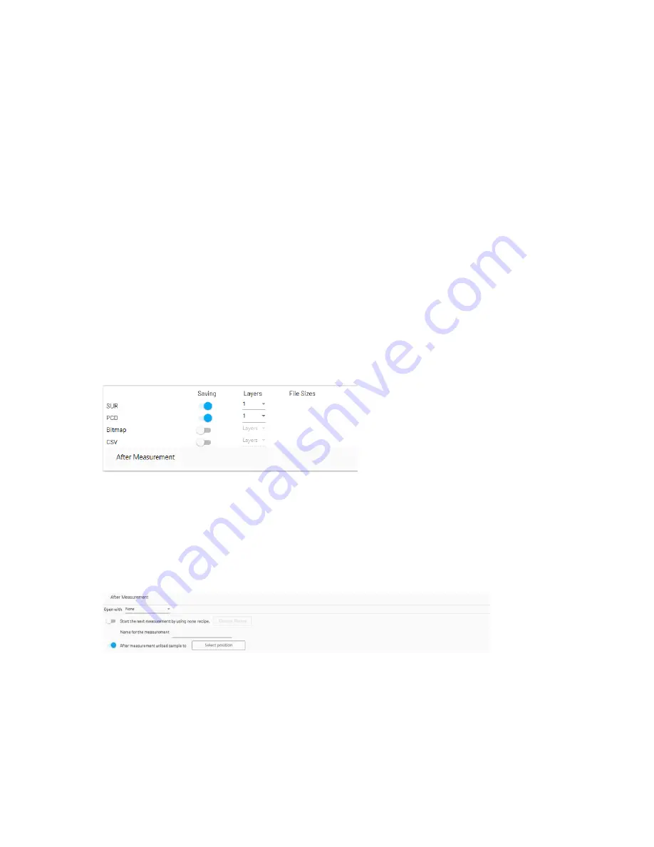
Output
— Settings related to the measurement output. The
Output
parameters screen is depicted in the figure
below:
The file format parameters are:
•
SUR
— Use the
.sur
file format.
•
PCD
— Use the
.pcd
file format.
•
Bitmap
— Use the
.bmp
intensity file format.
•
CSV
— Use the
.csv
file format to present XYZ intensity in the ASCII format.
Regardless of the file type selection or selections, always select the
Layers
, from which data will be saved. Lower
layers are applicable in the case of transparent materials.
File Sizes
indicates the size of the desired output file.
•
After measurement
— The actions to be carried out after the measurement has been completed. The
Output
parameters screen is depicted in the figure below:
The
After Measurement
parameters are:
•
Open with
— Select the program that will open the scan result once the scanning is completed. The options
are:
•
None
•
PCD viewer
•
CloudCompare
•
FS/MM Map
Figure 34 Output Parameters
Figure 35 After Measurement


