background image

42

BRAKES

See video on our website on how to adjust: www.lithiumcycles.com/pages/owners or Tektro brake 

adjustment manuals on www.tektro.com

For optimum braking performance, Super 73 bikes are equipped with Tektro mechanical or hydraulic 

disc brakes. The Super 73 bikes are assembled as follows:

•  Front brake = right lever

•  Rear brake = left lever

Using the same disc, braking performance is similar between a mechanical or hydraulic disc brake, but 

there are some differences in operation:

On a 

hydraulic disc brake

, pad wear is compensated automatically. Simply check the alignment of the 

pads with the disc, and check that the wheel is fully pushed back. Good alignment ensures the absence 

of noise and a normal wear of the pads. To see how how to adjust your hydraulic brakes, please visit our 

Support page on our website: www.lithiumcycles.com

The wear of the pads on a 

mechanical disc brake

 can be regulated by unscrewing the cable tension 

knob. There is a complementary adjustment of the inner pad which can be tightened closer or removed 

from the disc by screwing it in or out with a 5 mm Allen key. For more information on how to adjust 

brakes, see our website www.lithiumcycles.com and our You Tube channel.

To ensure maximum service life of the brake components, avoid contamination of the pads and the disc 

by greasy substances.

Regularly check the condition of your cables, ducts or harness and the wear of your pads. Some discs 

are only compatible with “resin” pads. Do not use a metal pad with discs marked “Resin”.

For better ergonomics and safety, we advise you to adjust the brake levers in a position that places it 

as a natural extension of the user’s arms. If you have any questions or concerns, please contact your 

retailer.

Break-in period

Disc brakes have a 30-40 cycle break-in period to achieve optimal pad seating and performance. Exer-

cise caution for the first 30-40 cycles each time your replace the brake pads. If you notice a squeal-like 

sound at the beginning, it’s normal. The brakes are naturally adjusting. Depending on the frequency of 

use, you may need to replace the brake pads. 

Replacing the pads

When pads are worn, make sure to adjust both clearances between the rotor and pad so that they are 

equal to 0.3 mm. If only one side is adjusted it will cause braking failure. 

1. Pads and pad holders are held in place by a 3 mm pad retainer bolt on the caliper. To remove the 

pads and pad holder, unscrew the retainer bolt, then gently push out the pads and holder. This may be 

easier to achieve by using the Allen wrench. 

2. Once free of the caliper, the pads may be easily removed from the pad holder. 

!

!

!

!

We recommend using our recommended brand of spare parts, or the original manufacturer parts for 

replacement of used components.

DANGER!

Summary of Contents for Super 73 SG

Page 1: ...User manual Assembly maintenance and warranty Original Instructions English Model Super 73 S series EN 2018 v 13...

Page 2: ...with the purchase of a Super 73 We look forward to hearing about your experience and seeing you online on our social networks www instagram com super73 www facebook com lithiumcycles CONTACT US MANUFA...

Page 3: ...of a Super 73 S 9 Included tools and hardware 10 Tools 11 Assembly Instructions 35 Before the first ride 36 Operating the bike 37 Lights 38 Maintenance Schedule 39 General Warnings Wet weather Riding...

Page 4: ...km h and a 250 Watt motor power output Principles of operation of a pedelec Your power assisted bike is assisted This means that according to the legislation you have to pedal continuously for assist...

Page 5: ...anics of the person to execute them require the use of additional specific tools or rely on prerequisites not described in this guide This manual includes assembly and maintenance work which may need...

Page 6: ...aintenance please go to our website www lithiumcycles com pages owners REGISTER YOUR SUPER 73 All original owners must register on our website to validate warranty Please register online at https www...

Page 7: ...are not properly rectified Similarly no liability and warranty shall be accepted in the case of assembly errors willful intent accidents and or if care and maintenance specifications are not followed...

Page 8: ...tery Seat Chain guard Cargo rack Pedals Dropouts Fenders Steering tube with triple tree fork Top fork section and handlebars Lower fork section Brake discs All terrain knobby tires DIAGRAM OF A SUPER...

Page 9: ...2 in kit 1 pre installed to secure shipping plug 2 in kit Pre installed on front wheel Un installed for safe shipping Used to install front brake rotor Used to secure cables Used to secure cables Left...

Page 10: ...ers 2 1 6 4 3 5 7 Before performing any work on your Super 73 turn off the power system and remove the battery Be sure to also turn off the power system and remove the battery during transport in a ve...

Page 11: ...ents in the pack aging placing them on a flat surface HARDWARE box cutter scissors or blade REMOVE THE BATTERY PRIOR TO ASSEMBLY DANGER Please follow the instructions carefully to ensure the proper fu...

Page 12: ...d follow these operating instructions Do not leave the battery connected to the active charger for more than 48 hours Do not leave the charger connected to a socket for more than 48 hours Charge the b...

Page 13: ...the top half of the fork and the front wheel remove both from their packaging ACTION Inflate both the front and rear tires Use this diagram as a guide to help you seat the bead of the tire properly o...

Page 14: ...the wheel Assembly Tip Hand tighten the torx screws before using the wrench HARDWARE 5 4mm Torx wrench H Front rotor Torx screws and G Front brake rotor ACTION Inflate the tires Tires must be inflated...

Page 15: ...ttention to the directional arrow on the rotor This arrow should be pointed in the same direction as the wheel spins during operation 6 ACTION Loosen the front wheel axle nuts in preparation for insta...

Page 16: ...lic brakes remove the brake pad spacer before attaching the front wheel Insert the front axle into the front dropouts Make notice of the front rotor as it has to seat properly into the front brake cal...

Page 17: ...17 Your bike should look like this 8 ACTION Remove the middle triple tree bolt and set aside with the others HARDWARE 2 8 Adjustable crescent wrench 3 8mm Hex wrench...

Page 18: ...hen the top half of the fork is removed It helps stabilize the fork assembly ACTION Lift the rear end of the bike pivoting it on the kickstand This will help prevent separation of the headset componen...

Page 19: ...embly stays in place HARDWARE 3 8mm Hex wrench EXPLODED VIEW This is what the headset components look like Make sure they are kept in this order Keep one hand underneath to keep components in place AC...

Page 20: ...precise and tight fit This is the part of the assembly that can be fairly diffi cult and a little force is required 13 ACTION With the rear end up lightly tighten the steer tube bolt with the spacers...

Page 21: ...ple tree bolts D Triple tree lock nuts E Triple tree lock washers 14 ACTION Install and lightly tighten the outer two triple tree bolts that were previously set aside in step 11 Use the washers with t...

Page 22: ...uded in your model Insert the triple tree bolt into the light bracket HARDWARE C Triple tree bolt ACTION Insert bolt into the front center triple tree hole Lightly install lock washer and nut HARDWARE...

Page 23: ...Fully tighten the steering tube bolt Rotate the handle bars to make sure the bolt is not too tight It should be tight but still rotate with ease HARDWARE 3 8mm Hex wrench 17 ACTION Adjust the headligh...

Page 24: ...24 Your bike should now look like this Tighten all triple tree bolts...

Page 25: ...25 18 ACTION Adjust the display throttle to desired angle and tighten HARDWARE 6 3mm Hex wrench...

Page 26: ...ike model you may have mechanical brakes or hydraulic brakes They look like these be low Follow the instructions according to the model you have Mechanical brake lever Mechanical brakes assembly go to...

Page 27: ...line goes to the RIGHT brake lever On European models the brake levers are set the opposite way the REAR wheel brake line goes to the RIGHT brake lever and the FRONT wheel brake lines goes to the LEF...

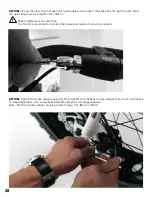
Page 28: ...in Brake cables wear out over time It is therefore essential to maintain them well and replace them when needed ACTION Tighten the brake calipers using 4 5mm Hex Wrench Brakes are pre adjusted For mor...

Page 29: ...29 ACTION First unwrap the brake lines and wires from the frame Adjust brake levers to desired angle and tighten HARDWARE 7 4mm Hex wrench 20...

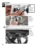
Page 30: ...nes ACTION Connect the wiring harness plugs into their corresponding connectors RED TO RED YELLOW TO YELLOW BLACK TO BLACK 21 WIRING HARNESS Rear brake cable Front brake cable ACTION Connect head ligh...

Page 31: ...able guide clips Your cable guide clips should be secure and look like this 22 ACTION Attach harness cable to the cable guides shown below Keep the zip ties slightly loose until the cable is in the co...

Page 32: ...32 Proper configuration of cables with hydraulic brakes...

Page 33: ...33 Proper configuration of cables with mechanical brakes...

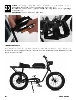
Page 34: ...a clockwise direction The left pedal is screwed on by turning it counter clockwise HARDWARE 1 15mm Pedal wrench K pedals ASSEMBLY IS FINISHED You re almost ready to ride Your Super 73 should look like...

Page 35: ...in To learn more about adjusting brakes go on our website our YouTube channel or visit your local bike shop to have them professionally adjusted and tuned Check that the configuration of the brake lev...

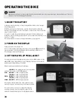
Page 36: ...display screen will light up 3 SET YOUR LEVEL OF PEDAL ASSIST To select your level of pedal assist press on the M button or the and arrow depending on your display You have 3 5 levels of pedal assist...

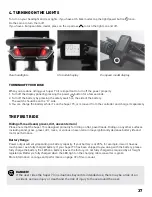
Page 37: ...attery If your Super 73 has been shipped to you along with the battery please fully charge the battery first When a battery leaves the factory it s not fully charged as required by air freight legisla...

Page 38: ...r to make a thorough check For your own safety take your E Bike for its first inspection with your specialist dealer after 200 to 400 km 125 to 250 miles or at the latest after three months WASHING AN...

Page 39: ...ed such as opening car doors or cars backing out of driveways Be aware at intersections and when preparing to pass other vehicles or other cyclists Familiarize yourself with all the bike features Prac...

Page 40: ...nditions Wear appropriate safety gear and do not ride alone in remote areas Bicycles and bicycle parts have strength and integrity limitations and extreme riding should not be performed or you risk da...

Page 41: ...us injury make sure all air pressure has been removed from the inner tube before removing the tire from the rim In addition to proper inflation correct wheel alignment helps to decrease tire wear If y...

Page 42: ...tamination of the pads and the disc by greasy substances Regularly check the condition of your cables ducts or harness and the wear of your pads Some discs are only compatible with resin pads Do not u...

Page 43: ...o not dispose the battery in your trash There are proper disposal methods for lithium ion batteries Please check your local waste management regulations Warning Lithium ion battery transportation is s...

Page 44: ...floor CAUTION Do not open the battery There is a risk of short circuit Opening the battery will void the warranty Protect the battery against mechanical damage heat in case of prolonged exposure to su...

Page 45: ...or a distributor s website All disassembly and shipping costs incurred will be the sole responsibility of the owner This warranty is only valid for the first buyer Any other remedy such as compensatio...

Page 46: ...their function Check the condition of the pads regularly and if necessary have them replaced by a specialist dealer Brake discs also wear out Regularly have the thickness of the brake discs checked a...

Reviews: