


Service/Repair
Grinding machine SBM-XS 300 G1E1 ALU MIX
45
7.5 Cleaning
interval
These daily cleaning tasks of the machine is to be recorded in writing in the
cleaning record.
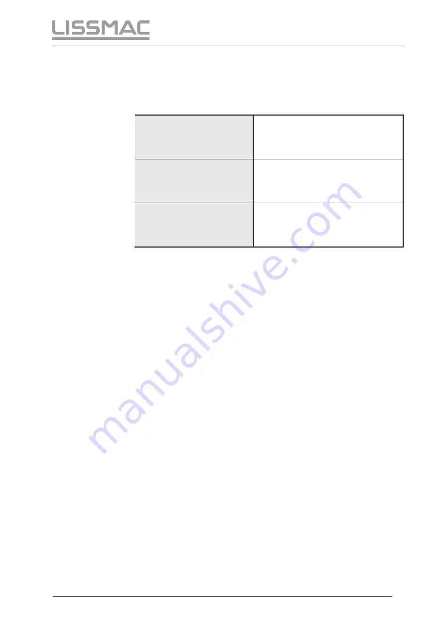
Machining of aluminium
The machine must be cleaned
completely every three hours (see 7.4)
Machining of steel
The machine must be cleaned
completely every eight hours (see 7.4)
Material switch from steel
(stainless steel) to
aluminium or vice versa
The machine and the suction pipes
must be cleaned completely (see 7.4)
Summary of Contents for SBM-XS 300 G1E1 ALU MIX
Page 2: ......
Page 14: ...Safety 14 Grinding machine SBM XS 300 G1E1 ALU MIX Notes...
Page 53: ......