background image

ioPower User Guide                                                                                                               Quick Installation  

Rev. 1.41      Copyright© All rights reserved.   

Feb 2005


3


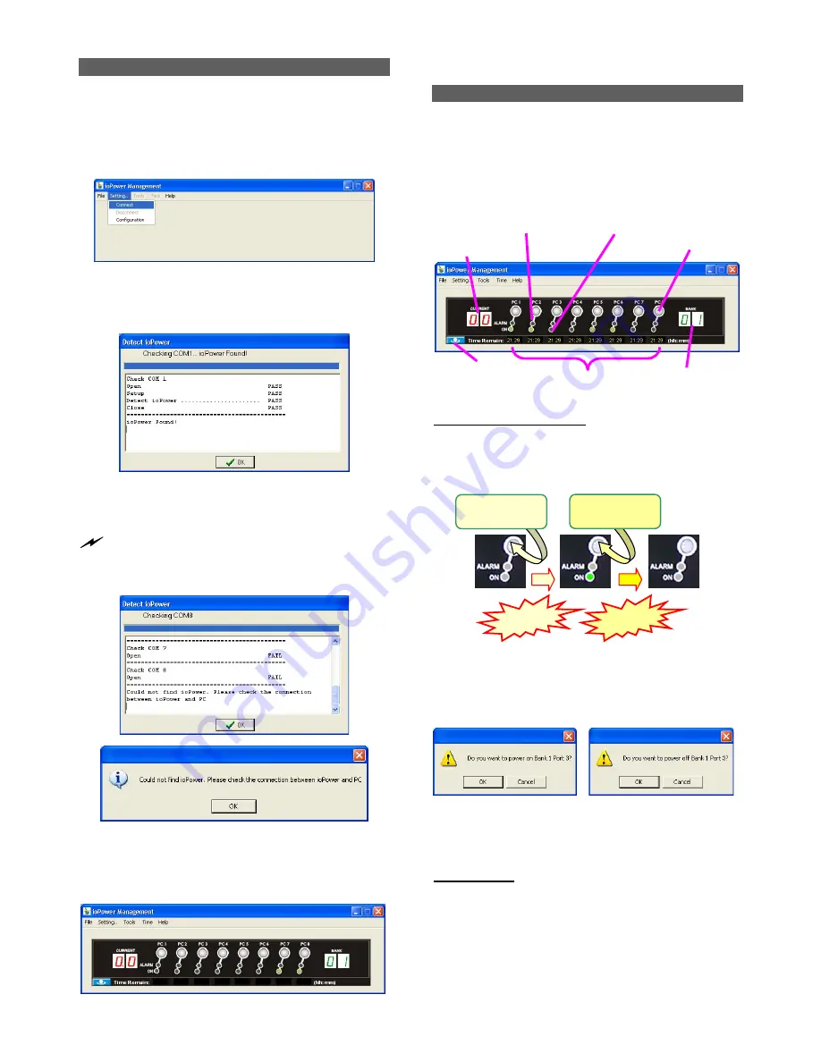
Connect host PC to ioPower 

 
Now you can begin connecting your ioPower to the host 
PC 
 
Step 1

. Run the ioPower Management software by double-

clicking its desktop icon or access 

Start /programs 

/ioPower/ioPower Management


Step 2.

 Connect the host PC to 

ioPower

 by clicking 

Setting/Connect

. And the software will automatically detect 

COM port for 

ioPower

…. 


Check the COM port detection message on the message 
Box. After the COM port has been successfully detected, 
click 

OK

 to connect.


 Note that if you see the FAIL message such as in the following 

picture, it means you have a faulty connection. Check your physical 
COM port connection to make sure that everything is in place, 
including the connectors and RS-232 cable integrity, etc.  


Failure of COM port detection 

 
Step 3. 

Then you can see the virtual front panel of the 

connected 

ioPower

 unit(s). 


Now get yourself a little bit familiar with the Management 
Software interface ………. 
 

Power Management Software Interface 

 
When running the 

ioPower Management Software

, you 

should see a 

virtual front-panel 

identical to the physical front-

panel.  If you are cascading multiple units of 

ioPower


(using 

the RJ-45 daisy-chain interfaces connected by a UTP cable), 
you can then see a corresponding number of stacked virtual 
front-panels, each of which showing its bank number, the 
total current loads and 

time remaining

 status per port. 


Virtual front-panels showing a single unit 


Virtual front-panel operation 

 
The virtual front-panel serves just like a real front-panel to 
provide “

one-touch

” power on/off function. Just click each 

virtual button to switch the power on and off 


Powered Off          Powered-On            Powered-Off 


However, to avoid accidental mistakes, 


ioPower 

Management software

 will, by default, pop up a prompt for 

confirmation of this change after you click the virtual power 
button. 


Power on/off confirmation dialog prompt 

 
User can have free choice to disable/enable the confirmation 
prompt according one’s convenience. 


Menu Function 


File/Exit (Ctrl-X) 

To exit the management program, click 

File/Exit 

or use the 

hotkey, 

Ctrl-X


Setting/Connect 

When 

ioPower

 is disconnected with host PC, click 

Setting/Connect

 to connect to host PC. 


Time Remain 

Current Loads Display 

Global Power Action Button 

Bank Number Display 

Power Button 

Alarm LED (Red)    Power ON LED (Green) 

Release! 

Release! 

Press and hold  

for 2 “ …. 

Press and hold  

for 2 “ …. 

Summary of Contents for ioPower

Page 1: ...ioPower 8 port Remote Power Control Unit for any AC powered Devices Servers User Guide Rev 1 41 Feb 2005...

Page 2: ...with this user s guide may cause harmful interference to radio communications Operation of this equipment in a residential area is likely to cause interference to household appliances in which case th...

Page 3: ...ioPower User Guide Table of Contents iii Table of Contents Table of Contents iii Quick Installation 1 Flash Upgrade Operation Guide Using Windows HyperTerminal 7 Serial Command Set 10...

Page 4: ...that fits the standard power outlets on the backpanel of ioPower Features Hardware Can be used alone or cascaded with multiple units for power control of 8 to 100 more AC powered devices Unit manageme...

Page 5: ...panel Rear panel for the US Region Rear panel for the EU Region You might need to use extra adapter cords between ioPower and your devices especially when the devices are not of the plug specification...

Page 6: ...front panel identical to the physical front panel If you are cascading multiple units of ioPower using the RJ 45 daisy chain interfaces connected by a UTP cable you can then see a corresponding number...

Page 7: ...ore the last known port status of each port when ioPower unit is restarted Tools Upgrade Once ioPower firmware upgrade is available you can either get it from your local dealer or download it from ava...

Page 8: ...utes to go for a Power On on all ports Note that the timer settings will also be executed nonetheless when 1 the host PC is shut down or 2 the ioPower Management Software is disconnected to the ioPowe...

Page 9: ...persistently If so it indicates that this port is malfunctioning for good and need technical service from your local dealer Port Error unable to power on Port Error unable to power off While an alarm...

Page 10: ...l computer You can copy them from the diskette CD ROM provided by the technical support or download it from available support website Check the connection between the ioPower Unit and PC Make sure you...

Page 11: ...he next step Flash Upgrade File Transfer Step 7 To start loading the file access the drop down menu on HyperTerminal Transfer Send Text File and a dialog box will prompt you to select the flash upgrad...

Page 12: ...nit Wait for a few seconds and then complete the reset again Troubleshooting If the flash upgrade procedure seems never ending or you see the following message Please send new firmware shown on the sc...

Page 13: ...require a strict double digit entry of bank number or port number such as ON 01 03 Power on bank 1 port 3 but can accept their single digit entries such as ON 1 3 and also allow multiple blank spaces...

Page 14: ...rn on off a specific port at specific time Usage TA bank_number port_number ON OF Time_point Examples TA 1 4 ON 01 22 50 Set timer to power on port 4 on bank 1 exactly at 01 22 50 TA 1 0 ON 00 10 00 S...

Page 15: ...r to power on all ports on bank 1 exactly every Wednesday at 00 10 00 EW 0 0 OF 5 01 00 00 Set timer to power off all ports on all cascaded banks every Friday at 01 00 00 Notes 1 A port number of 0 re...

Page 16: ...E Example UPGRADE Note Please also refer to ioPower Flash Operation Guide for details SETTIME Set Up System Date and Time Description Set up the system date and time Usage SETTIME 20yy mm dd hh mm ss...

Reviews: