


D9S001GE4-0101
8/
57
3.1.2
Technical parameters
3.1.3
Control unit
The PB43 red unit is used for
controlling
4 linear units, with outputs for controllers and a
backup
rechargeable battery
power source. It is controlled via low-voltage switches and allows the use of membrane keypads. The control unit has
4 outputs for the linear units, an input for connecting a rechargeable battery, and an input for control panels with safety
functions (ACP). The PB43 red unit also contains inputs for weight transducers, an undercarriage module, limit
switches, and an add-on matrix controller. The PB43 red unit is built into the instrument case and is equipped for dual
power from the
mains
and from
batteries
. During mains operation, the rechargeable battery is continuously powered
and charged, and while the rechargeable battery is in operation, the electronics are
disconnected
after approximately
3 minutes
without command. The control unit has a function to
synchronise speed
of the lift units (see
Synchronisation (calibration) of speed of lift units) of the mattress platform, and to lock the units (See If resistance is
movement of the bed after the STOP button is pressed. Information about the leak is
permanent memory of the control unit.
Positioning function locks and safety circuit to detect overload (See Detecting overload).
3.1.4
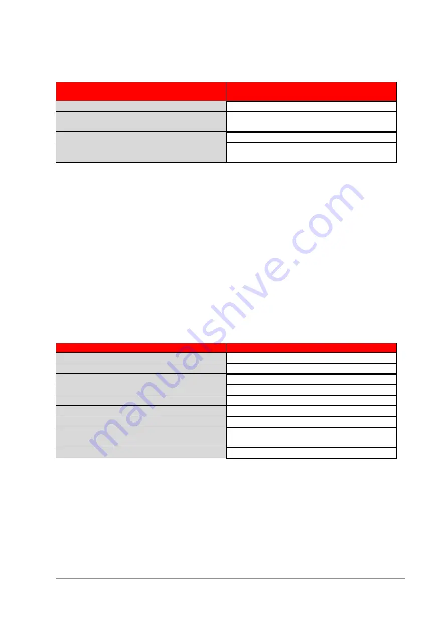
Technical parameters
Parameters
Values
Dimensions:
310 x 125 x 90
Cover:
IP54
Number of outputs for motor units:
4
Output current for motors:
5 A
Current load of any motor output during positioning:
less than or equal to 5 A
Maximum voltage at outputs for motors idling:
42 V DC
Maximum performance:
internally limited
Maximum tolerance of configuration
of current limitation:
±20%
Number of control buttons (functional inputs)
30 - basic matrix 6 x 5
3.1.5
Control unit modes and safety functions
The architecture of the control unit is designed to exclude or significantly limit the risks arising from using a
programmable electronic system.
The default general requirement is the
safety
of the
system
when there is one fault. The basic safety features are:
3.1.5.1
Synchronisation (calibration) of speed of lift units
The function to stabilise speed of lift units allows
the speed
of lift of all columns to be
synchronized.
This makes it
possible to maintain the bed in a horizontal position. Synchronisation
must be performed
after each change of
column, control unit, and accelerometer
.
Parameters
Values
Nominal supply voltage:
AC 230, 100, 110, 127V
(±10%) / 50-60 Hz
Fuse protection:
2 x tube fuse 5 x 20mm
T1,6A for 230V; T3,15A for 100-127V
Maximum performance:
internally limited
Maximum tolerance of configuration
of current limitation:
±20%
Summary of Contents for Wissner-Bosserhoff ELEGANZA 4
Page 5: ...D9S001GE4 0101 5 57 Identification of bed sides...
Page 18: ...D9S001GE4 0101 18 57 Weight module and tensometers S6015189ND...
Page 31: ...D9S001GE4 0101 31 57 i Drive Power connection scheme...
Page 34: ...D9S001GE4 0101 34 57 Castors Castors Antistatic castor Castor with lock Central Castor Control...
Page 35: ...D9S001GE4 0101 35 57 Bed Wiring Diagram...
Page 45: ...D9S001GE4 0101 45 57 The CAL position displays the calibration constant...
Page 49: ...D9S001GE4 0101 49 57 5 3 6 4 Positioning the weights for sensors 2 head left sensor...
Page 51: ...D9S001GE4 0101 51 57 5 3 6 6 Positioning the weights for sensor 3 left foot sensor...
Page 53: ...D9S001GE4 0101 53 57 5 3 6 8 Positioning the weights for sensor 4 right foot sensor...