Linear Acoustic UPMAX ISC Manual Download Page 20

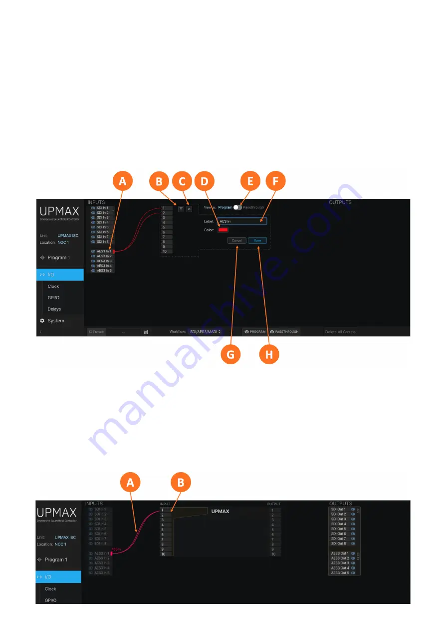
If the channels in the input group are destined to be upmixed, select “Program” in the View as switch (5-3E). 
If the input group is being established only to pair shuffle or to pass through content without upmixing, 
choose “Passthrough.”

To quickly route a physical channel pair to the corresponding input to the upmixer – for example, to route 
AES 7/8 to input 7/8 of the upmixer – you may click on the Align button (5-3B) in lieu following the steps 
below for routing. Clicking the Clear All button (5-3C) acts as an “escape” button in case you need to start 
over.

Click the Save button (5-3G) to save the configuration or the Cancel button (5-2H) if you need to start over 
without saving your configuration.

Figure 5-3 - Creating an input group

Routing Audio to the Upmixer Input

After creating and saving the input, it is necessary to route the physical audio input pair to the input of the 
upmixer. Click on the input audio pair (5-4A), drag the lines to the desired upmixer input pair (5-4B), then 
release the left mouse button.

Summary of Contents for UPMAX ISC

Page 1: ...qually at home in the airchain at the Network Operations Center NOC to ensure all programming including commercials and interstitial content is delivered to the viewer as a consistent immersive experi...

Page 2: ...ly presented in an immersive format It is equally at home in the airchain at the Broadcast Operations Center BOC to ensure all programming including commercials and interstitial content is delivered t...

Page 3: ...Additional configuration is accomplished via the remote user interface UPMAX ISC Rear Panel Figure 2 Rear panel The rear panel includes the following connections Two RJ 45 Gigabit Ethernet connections...

Page 4: ...cern Accordingly each supply should be fed from a different circuit equipped with adequate surge protection and fitted with an uninterruptable power supply UPS Boot Up and Splash Screen The unit will...

Page 5: ...o move to the first digit of the IP address Use the Up Down buttons to change the value Use the Right Left buttons to select another digit to edit When finished editing the Address field press the Rig...

Page 6: ...inputs and outputs on female BNC connectors plus AES67 I O via the AES67 Ethernet port Connect the physical inputs and outputs as appropriate for your installation Connecting to the Web Based User In...

Page 7: ...1234 into the Password field 6B then click the Log In button 6C The ability to change the password will be included in an upcoming software update UPMAX ISC User Manual V1 0 54 Applicable to V1 04 54...

Page 8: ...section Connecting to UPMAX ISC via the web based user interface covered in the section provides easier navigation and full control of the unit Installation and Initial Setup Using the Front Panel In...

Page 9: ...urround Right Surround Ls Rs 7 8 Left Front Height Right Front Height Tfl Tfr 9 10 Left Rear Height Right Rear Height Tbl Tbr GPI O The active state for GPI is Low and is internally pulled up through...

Page 10: ...plies protected by type T1AL25V fuses Remember that while redundant supplies do protect against the unit losing power in the event of a PSU failure the loss of mains supply voltage is a bigger concern...

Page 11: ...tes an inactive or missing reference Home screen The Information Screen Pressing the Right button navigates to the Information screen The name of this particular UPMAX ISC and its location are display...

Page 12: ...fixed IP address will be preferred in most cases and can be set as follows Press the OK button to highlight Edit Press OK again to highlight Use DHCP Press the Right button to highlight Yes Press the...

Page 13: ...e the Locate Mode from the remote user interface the unit s front panel display will repeatedly change color until Locate Mode has been cleared by pressing any key on the front panel or by clicking ag...

Page 14: ...d to be connected to a network and operated through its web based interface IMPORTANT As explained in detail in the section UPMAX ISC must be connected to 1000BASE T Gigabit switch ports and the Contr...

Page 15: ...rameters via the remote user interface requires logging into the unit At this time only one level of access with is supported Enter the default password 1234 in the password field 4 1G and click on th...

Page 16: ...menu field will appear blank until a user preset is created and saved Clicking on the Preset management icon 4 3D reveals a dropdown menu with the following options Save Saves the current Program 1 se...

Page 17: ...displayed on the input meters 4 3F and output meters 4 3I The most commonly used controls for the upmixer are shown in the Basic controls portion of the screen 4 3G The Advanced controls menu 4 H is c...

Page 18: ...saved and recalled in the Preset menu 5 1B Clicking on the I O Preset management icon 5 1C reveals a dropdown menu with the following options Remote User Interface Save Saves the current I O settings...

Page 19: ...it delete all groups simultaneously Figure 5 2 Signal routing menu Creating an Input Group Click on your first audio input source 5 3A to highlight it then right click and select Create Input Group Yo...

Page 20: ...ton 5 3B in lieu following the steps below for routing Clicking the Clear All button 5 3C acts as an escape button in case you need to start over Click the Save button 5 3G to save the configuration o...

Page 21: ...this control Remove All Assignments Clears all current channel mapping for the selected input audio pair Edit Group Allows the input name and color to be changed Delete Group Completely clears the inp...

Page 22: ...Pin Function Pin Function Pin 1 5VDC Pin 9 5VDC Pin 2 GPI 1 Pin 10 GPO 1 Pin 3 GPI 2 Pin 11 GPO 2 Pin 4 GPI 3 Pin 12 GPO 3 Pin 5 GPI 4 Pin 13 GPO 4 Pin 6 GPI 5 Pin 14 GPO 5 Pin 7 Ground Pin 15 Status...

Page 23: ...ring an even frame value will result in a situation where it is necessary to add additional audio delay to the AES67 and AES 3 outputs so that they match the timing of the SDI output signal This can b...

Page 24: ...mats having a firm grasp of the clock sync reference requirements is critical Clock Reference Requirements Sample Rate Converters SRCs are provided on both SDI inputs the SDI 1 output and the AES 3 in...

Page 25: ...perate in slave mode by default There are controls in the Sync QoS sub menu of the System menu to change this should the ability to operate as a clock master be introduced in future software versions...

Page 26: ...Unit Hardware Relay Bypass Recall Preset Recall I O Preset GPO Events 5 10E include None GPI Passthrough Power Supply 1 up Power Supply 2 up Power Supply 1 down Power Supply 2 down Unit resetting Uni...

Page 27: ...nd explanation of the upmixing controls UPMAX ISC uses the latest Linear Acoustic upmixing algorithm for upmixing from 2 3 5 1 and 7 1 channel audio to immersive formats including 5 1 2 5 1 4 and 7 1...

Page 28: ...xed to the desired output format while a dedicated dialog input on Channel 3 will be passed through to the Center output 5 1 5 1 channel content will be upmixed to the desired output format Pass throu...

Page 29: ...onstant 5 1 channel output from Stereo Stereo Dialog and 5 1 channel input sources but with upmixing that is sonically closer to the previous UPMAX algorithm used in the Linear Acoustic UPMAX v4 upmix...

Page 30: ...Left and Right soundstage This can be very useful in keeping the main phase correlated signal HF band in the Center Channel for dialog while spreading the lower frequency portion of the Center channe...

Page 31: ...ding a pleasant and wide image of the phase correlated elements Values are expressed in a decimal format but easily correlate to a percentage value 0 00 0 0 50 50 1 00 100 etc The LF Center Width cont...

Page 32: ...proper setting depends largely on the quietness or noisiness of channels that are not muted but also contain no audio Set too low it may cause a false trigger to upmix set too high it may cause a late...

Page 33: ...equency change of the comb filter The comb filter is used to separate different frequency components of the input signal to aid in steering sounds in the surround field Minimum Comb Filter Frequency T...

Page 34: ...on the downmix but can have a great effect on the upmixed presentation Front High Crossover The Front High Crossover control 6 6G adjusts the crossover point between the Front Left and Right channels...

Page 35: ...eights control 5 6M determines to what degree lower frequencies from the ear level to height speaker crossover circuit are mixed back into the height speakers when upmixing to 5 1 4 and 7 1 2 output f...

Page 36: ...Figure 6 6 Advanced menu controls...

Reviews: