background image

A-11

INSTALLATION

VANTAGE

®

520 SD

CABLE INDUCTANCE AND ITS EFFECTS ON
WELDING

Excessive cable inductance will cause the welding performance to
degrade. There are several factors that contribute to the overall
inductance of the cabling system including cable size, and loop
area. The loop area is defined by the separation distance between
the electrode and work cables, and the overall welding loop
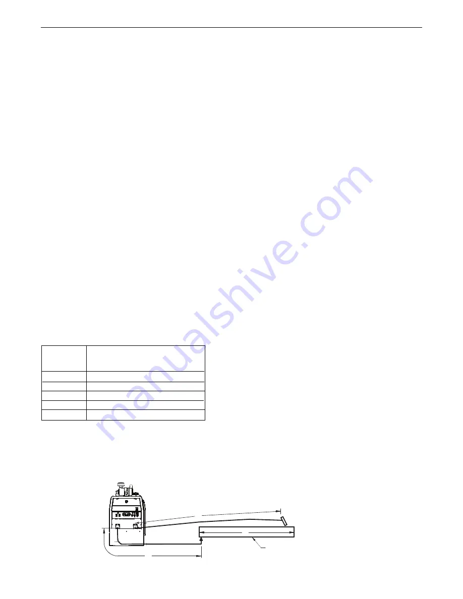
length. The welding loop length is defined as the total of length of
the electrode cable (A) + work cable (B) + work path (C) (See
Figure A.9). 

To minimize inductance always use the appropriate size cables,
and whenever possible, run the electrode and work cables in close
proximity to one another to minimize the loop area. Since the most
significant factor in cable inductance is the welding loop length,
avoid excessive lengths and do not coil excess cable. For long
work piece lengths, a sliding ground should be considered to keep
the total welding loop length as short as possible.

Electrode Voltage Sensing

The remote ELECTRODE sense lead (67) is built into the 5-pin
ArcLink control cable and is always connected to the wire drive
feed plate when an ArcLink wire feeder is present. Enabling or
disabling electrode voltage sensing is application specific, and
automatically configured by the active weld mode.

Voltage sense leads requirements are based on the weld process
(See Table A.3).

CONTROL CABLE CONNECTIONS

General Guidelines

Genuine Lincoln control cables should be used at all times (except
where noted otherwise).  Lincoln cables are specifically designed
for the communication and power needs of the 

Engine Welder and

Power Feed

systems. Most are designed to be connected end to

end for ease of extension.  Generally, it is recommended that the
total length not exceed 200ft. (60.960m). The use of non-standard
cables, especially in lengths greater than 25 feet, can lead to
communication problems (system shutdowns), poor motor accel-
eration (poor arc starting), and low wire driving force (wire feeding
problems). Always use the shortest length of control cable possi-
ble, and 

DO NOT coil excess cable.

Regarding cable placement, best results will be obtained when
control cables are routed separate from the weld cables. This min-
imizes the possibility of interference between the high currents
flowing through the weld cables, and the low level signals in the
control cables. 

Product specific Installation Instructions

Connection Between VANTAGE

®

520 SD and ArcLink

®

Compatible

Wire feeders  (K1543, K2683 – ArcLink

®

Control Cable)

The 5-pin ArcLink

®

control cable connects the VANTAGE

®

520 SD

to the wire feeder. The control cable consists of two power leads,
one twisted pair for digital communication, and one lead for voltage
sensing. The 5-pin ArcLink

®

connection on the VANTAGE

®

520 SD

is located on control panel. The control cable is keyed and polar-
ized to prevent improper connection. Best results will be obtained
when control cables are routed separate from the weld cables,
especially in long distance applications. The recommended com-
bined length of the ArcLink

®

control cable network should not

exceed 200ft. (60.960m).

FIGURE A.9

B

A

C

WORK

VANTAGE


520 SD

Process

GMAW

GMAW-P

FCAW

GTAW

SMAW

Electrode Voltage Sensing 

(1)

67 lead

67 lead 

67 lead 

67 lead 

Voltage sense at studs

Voltage sense at studs

TABLE A.3

(1)

The electrode voltage sense lead (67) is automatically

enabled by the weld process, and integral to the 5 pin

ArcLink control cable 

(K1543-xx) or K2683-xx.

Summary of Contents for VANTAGE 520 SD

Page 1: ...achines having Code Numbers 12297 Need Help Call 1 888 935 3877 to talk to a Service Representative Hours of Operation 8 00 AM to 6 00 PM ET Mon thru Fri After hours Use Ask the Experts at lincolnelectric com A Lincoln Service Representative will contact you no later than the following business day For Service outside the USA Email globalservice lincolnelectric com Save for future reference Date P...

Page 2: ...the general area IN A LARGE ROOM OR OUTDOORS natural ventilation may be adequate if you keep your head out of the fumes See below USE NATURAL DRAFTS or fans to keep the fumes away from your face If you develop unusual symptoms see your supervisor Perhaps the welding atmosphere and ventilation system should be checked WEAR CORRECT EYE EAR BODY PROTECTION PROTECT your eyes and face with welding helm...

Page 3: ...ty guards covers and devices in position and in good repair Keep hands hair clothing and tools away from V belts gears fans and all other moving parts when starting operating or repairing equipment 1 e In some cases it may be necessary to remove safety guards to perform required maintenance Remove guards only when necessary and replace them when the maintenance requiring their removal is complete ...

Page 4: ...o ANSI Z87 I standards 4 b Use suitable clothing made from durable flame resistant material to protect your skin and that of your helpers from the arc rays 4 c Protect other nearby personnel with suitable non flammable screening and or warn them not to watch the arc nor expose themselves to the arc rays or to hot spatter or metal FUMES AND GASES CAN BE DANGEROUS 5 a Welding may produce fumes and g...

Page 5: ... lifting chains crane cables or other alternate circuits This can create fire hazards or overheat lifting chains or cables until they fail 6 h Also see item 1 c 6 I Read and follow NFPA 51B Standard for Fire Prevention During Welding Cutting and Other Hot Work available from NFPA 1 Batterymarch Park PO box 9101 Quincy Ma 022690 9101 6 j Do not use a welding power source for pipe thawing CYLINDER M...

Page 6: ...Feed 84 to VANTAGE 520 SD A 9 Connection of Across the Arc Wire Feeders to VANTAGE 520 SD A 10 Cable Inductance and its Effects on Welding A 11 Control Cable Connections A 11 Operation Section B Safety Instructions B 1 Recommended Applications B 1 Controls and Settings B 2 Engine Controls B 2 B 3 Stop Low Idle Run High Idle Run Switch B 2 Start Switch B 3 Dash Board Gauge B 3 Output Control B 3 VR...

Page 7: ... B 14 Simultaneous Welding and Auxiliary Power Loads B 14 Extension Cord Length Recommendations Tables B 15 Weld Set Reference Chart B 16 Accessories Section C Optional Field Installed Accessories C 1 Wire Feeder Options C 2 Maintenance Section D Safety Precautions D 1 Routine and Periodic Maintenance D 1 Engine Maintenance D 1 Air Filter D 1 Service Instructions Air Cleaner D 2 Fuel Filters D 3 C...

Page 8: ...8 NOTES VANTAGE 520 SD ...

Page 9: ...oads up to rated capacity When welding available auxiliary power will be reduced 2 Top of Enclosure Add 10 12 257 0mm for exhaust and air cleaner 3 Includes Door Base is 27 0 685 8mm wide OUTPUT 104 F 40 C WELDER AND GENERATOR Make Model K4107 1 Deutz D2 9L4 Naturally Aspirated Diesel Engine EPA TIER 4 Final Compliant Description 4 cylinder 34 8HP 25 9 kw Naturally Aspirated Water Cooled Diesel En...

Page 10: ...On or Off Turn the engine Off Disconnect the negative battery cable Lower the Front panel by removing 4 side panel screws See Figure A 1 Place the VRD switch in the On or Off position See Figure A 1 With the VRD switch in the OFF position the VRD lights are deactivated FIGURE A 1 LOCATION AND VENTILATION The welder should be located to provide an unrestricted flow of clean cool air to the cooling ...

Page 11: ... not operate machine while suspended from lift bale HIGH ALTITUDE OPERATION At higher altitudes output derating may be necessary For maxi mum rating derate the welder output in accordance with the guide lines in Table A 1 for this engine model from the manufacturer TABLE A 1 DEUTZ D 2 9 L4 ALTITUDE MAXIMUM POWER METERS FEET AVAILABLE 0 750 0 2461 99 1000 3281 95 2000 6562 95 3000 9842 93 4000 1312...

Page 12: ...ks and flame away from tank OIL The VANTAGE 520 SD is shipped with the engine crankcase filled with high quality SAE 10W 30 Oil that meets classification CJ 4 for diesel engines Check the oil level before starting the engine If it is not up to the full mark on the dip stick add oil as required Check the oil level every four hours of run ning time during the first 50 running hours Refer to the engi...

Page 13: ...NER INSTALL All parts below are shipped with the machine in a separate box attached to the crate See Figure A 2 Remove cap from air intake hose Tighten air hose clamp just below service indicator to hold clamp while pushing air cleaner onto hose 1 once hose is in place loosen air hose clamp slide down and tighten clamp Install 2 hex head screws washers using a 1 2 13mm wrench or socket to mounting...

Page 14: ...nly with an ArcLink compatible digital remote control through the 12 pin connector NOTE To connect accessories with a 6 pin connector use the included 12 pin to 6 pin adaptor K2909 1 WELDING TERMINALS The VANTAGE 520 SD is equipped with a toggle switch for selecting hot welding terminals when in the WELD TERMINALS ON position or cold welding terminals when in the REMOTELY CONTROLLED position When ...

Page 15: ...E 520 SD consists of two 20 Amp 120 VAC 5 20R duplex receptacles with GFCI protection one 50 Amp 120 240 VAC 14 50R receptacle and one 50 Amp 240VAC Three Phase 15 50R receptacle The auxiliary power capacity is 11 000 Watts Continuous of 60 Hz single phase power The auxiliary power capacity rating in watts is equivalent to volt amperes at unity power factor The max permissible current of the 240 V...

Page 16: ...censed electrician who can determine how the 120 240 VAC power can be adapted to the particular installation and comply with all applicable electrical codes Refer to the con nection diagram shown in Figure A 4 1 Install the double pole double throw switch between the power company meter and the premises disconnect Switch rating must be the same or greater than the customer s premises dis connect a...

Page 17: ...ect the electrode cable terminal of the welder and work cable to the terminal of the welder Set the MODE switch to the CV WIRE position Adjust the ARC CONTROL knob to desired Crispness SOFT for MIG and CRISP for Innershield Set the WELDING TERMINALS switch to the REMOTELY CONTROLLED position Set the wire feeder voltage switch to 42V Connect the 14 pin control cable from the wire feeder to the engi...

Page 18: ...der and work cable to the terminal of the welder For electrode Negative connect the electrode cable terminal of the welder and work cable to the terminal of the welder Attach the single lead from the front of the feeder to work using the spring clip at the end of the lead This is a control lead to supply current to the wire feeder motor it does not carry weld ing current See Figure A 8 Set the MOD...

Page 19: ... Feed systems Most are designed to be connected end to end for ease of extension Generally it is recommended that the total length not exceed 200ft 60 960m The use of non standard cables especially in lengths greater than 25 feet can lead to communication problems system shutdowns poor motor accel eration poor arc starting and low wire driving force wire feeding problems Always use the shortest le...

Page 20: ...A 12 NOTES VANTAGE 520 SD ...

Page 21: ...guards off Stop engine before servicing Keep away from moving parts Only qualified personnel should operate this equipment ADDITIONAL SAFETY PRECAUTIONS Always operate the welder with the sliding door closed and the side panels in place as these provide maximum protection from moving parts and insure proper cooling air flow RECOMMENDED APPLICATIONS WELDER The VANTAGE 520 SD provides excellent cons...

Page 22: ...hen switched from High to Auto or after starting the engine the engine will operate at full speed for approximately 12 seconds and then go to low idle speed b When the electrode touches the work or power is drawn for lights or tools approximately 100 Watts minimum the engine accelerates and operates at full speed c When welding ceases and the AC power load is turned off a fixed time delay of appro...

Page 23: ...t temperature 3c HOUR METER The hour meter displays the total time that the engine has been running This meter is a useful indicator for scheduling preventive maintenance 3d FUEL LEVEL Displays the level of diesel fuel in the fuel tank 3e BATTERY VOLTAGE INDICATOR Displays the battery voltage and indicates that the charging system is functioning properly 4 OUTPUT CONTROL The OUTPUT dial is used to...

Page 24: ...essed any time the machine is on with the engine running and not in a welding arc arc off or OCV To access press the hidden setup menu push button Figure B 4 with the appropriate tool or paper clip if no tool is readily available NOTE The menu system will exit automatically if any of the following conditions are met If no settings are changed for 10 seconds If the mode selection switch position is...

Page 25: ...visible if the process selection switch is in the CV Wire position Selection of the remote connector for stick SMAW modes The customer can select between the 12 pin or the 14 pin connector for the remote potentiometer input when in the remote switch position for stick SMAW modes The default from the factory will be the 12 pin connector The left display will show Pot 12P Figure B 9 and the right di...

Page 26: ...eset push button for 5 seconds will cause certain stored values to be reset to defaults The stored hot start values will return to a default setting of 5 on the display 0 at the attribute The work point values will all be reset to the minimum from the weld table for each respective weld mode The alternate CV mode selection will revert back to the Flux Cored Arc Welding Self Shielding FCAW SS setti...

Page 27: ...ROL be set initially at 0 10 WELD MODE SELECTOR SWITCH Provides six selectable welding modes CV WIRE DOWNHILL PIPE CC STICK TOUCH START TIG ARC GOUGES ARC LINK 11 42V 115V WIRE FEEDER VOLTAGE SWITCH Toggles output of 14 pin connector to voltage requirement of Wire Feeder Located above 14 pin connector 11a 42V and 115V WIRE FEEDER BREAKERS 12 5 PIN CONNECTOR For attaching an ArcLink Wire Feeder con...

Page 28: ...overload current pro tection for each 120V circuit at the 240V single phase recepta cle each 120V single phase receptacle the 240V three phase receptacle the 120VAC in the 14 Pin connector the 42VAC in the 14 Pin connector and battery circuit overload protection 25 GROUND STUD Provides a connection point for connecting the machine case to earth ground Refer to MACHINE GROUNDING in the Installation...

Page 29: ... normal for up to 15 seconds after power up or if the system configuration is changed during operation Indicates that one or more pieces of ArcLink equipment are not mapping properly Non recoverable system fault If the power source or wire feeder status LED is flashing any combination of red and green errors are present in the system Read the error code before the machine is turned off Instruction...

Page 30: ...nsumption of the VANTAGE 520 SD Engine for various operating scenarios TOUCH START TIG MODE The VANTAGE 520 SD can be used in a wide variety of DC TIG weld ing applications The TOUCH START TIG setting of the MODE switch is for DC TIG Tungsten Inert Gas welding To initiate a weld the OUTPUT CONTROL knob is first set to the desired current and the tungsten is touched to the work During the time the ...

Page 31: ...e material electrode size and shielding gas For a more complete description of the weld modes programmed into the VANTAGE 520 SD at the factory refer to the Weld Set Reference Guide supplied with the machine Wire Feed Speed WFS In synergic welding modes synergic CV GMAW P WFS is the dominant control parameter The user adjusts WFS according to factors such as wire size penetration requirements heat...

Page 32: ...ed speeds the adaptive range may be less due to reaching physical limitations of the welding process UltimArc Control adjusts the focus or shape of the arc UltimArc Control is adjustable from 10 0 to 10 0 with a nominal setting of 0 0 Increasing the UltimArc Control increases the pulse frequency and background current while decreasing the peak current This results in a tight stiff arc used for hig...

Page 33: ...0 15 30 6 8 13 17 5 7 11 15 6 7 8 3 2 1 8 250 400 25 40 7 11 15 23 5 7 11 15 4 0 5 32 400 500 40 55 10 12 21 25 6 8 13 17 8 10 4 8 3 16 500 750 55 80 11 13 23 27 8 10 18 22 6 4 1 4 750 1000 80 125 13 15 28 32 11 13 23 27 1 When used with argon gas The current ranges shown must be reduced when using argon helium or pure helium shielding gases 2 Tungsten electrodes are classified as follows by the A...

Page 34: ...machines in order to combine their outputs all units must be operated in the CC STICK mode at the same output settings To achieve this turn the WELD MODE switch to the CC STICK position Operation in other modes may produce erratic out puts and large output imbalances between the units AUXILIARY POWER OPERATION Start the engine and set the IDLER control switch to the desired operating mode Full pow...

Page 35: ...8 275 225 175 150 125 53 107 42 84 69 53 46 38 300 600 225 450 250 300 250 200 91 183 69 137 76 91 76 61 Maximum Allowable Cord Length in ft m for Conductor Size Conductor size is based on maximum 2 0 voltage drop 14 AWG 12 AWG 10 AWG 8 AWG 6 AWG 4 AWG TABLE B 5 VANTAGE 520 SD DEUTZ SIMULTANEOUS WELDING AND POWER LOADS WELD AMPS 0 100 200 300 400 up to 500 1 PHASE WATTS AMPS 11 000 46 11 000 46 80...

Page 36: ...ink feeder Synergic CV Modes Dia Steel Stainless Metal Core Flux Core Aluminum inches CO2 Argon Mix Argon Mix Tri Mix Argon Mix Argon Mix CO2 4043 5356 030 035 040 045 3 64 0 052 1 16 Pulse Modes Dia Steel Stainless Aluminum inches Argon Mix Argon Mix 4043 5356 0 035 0 045 3 64 0 052 1 16 ...

Page 37: ...fill and cap passes 6 and 14 pin remote connec tions can be made to this unit For all Lincoln Electric Chopper Technology engine driven welders Mounts on roof with K2663 1 Docking Kit K2642 1 K1816 1 Full KVA Adapter Kit Plugs into the 120 240V NEMA 14 50R receptacle on the case front which accepts 4 prong plugs and converts it to a NEMA 6 50R receptacle which accepts 3 prong plugs for connection ...

Page 38: ...ve rolls and inner wire guide for Steel Wires Used on LN 25 Pro K487 25 Magnum SG Spool Gun Hand held semiautomatic wire feeder Requires SG Control Module and Input Cable K488 SG Control Module The Interface between the power source and the spool gun Provides control of the wire speed and gas flow For use with a spool gun K691 10 Input Cable For SG Control Module For Lincoln engine power sources w...

Page 39: ...e above drainage procedure until diesel fuel is detected in the container WEEKLY Blow out the machine with low pressure air periodically In partic ularly dirty locations this may be required once a week ENGINE MAINTENANCE Refer to the SERVICE PLAN section of the Engine Operator s Manual for the recommended maintenance schedule of the following a Engine Oil and Filter b Air Cleaner c Fuel Filter an...

Page 40: ...tself and distribute the sealing pressure evenly To complete a tight seal apply pressure by hand at the outer rim of the filter not the flexible center Avoid pushing on the center of the urethane end cap No cover pressure is required to hold the seal NEVER use the service cover to push the filter into place Using the cover to push the filter in could cause damage to the housing cover fasteners and...

Page 41: ...with a catch only reservoir to keep any rejected or excess coolant from entering the environment Check periodically and empty as required Do not fill with coolant BATTERY HANDLING GASES FROM BATTERY can explode Keep sparks flame and cigarettes away from battery To prevent EXPLOSION when INSTALLING A NEW BATTERY disconnect negative cable from old battery first and con nect to new battery last CONNE...

Page 42: ...g time NAMEPLATES WARNING DECALS MAINTENANCE Whenever routine maintenance is performed on this machine or at least yearly inspect all nameplates and labels for legibility Replace those which are no longer clear Refer to the parts list for the replacement item number WELDER GENERATOR MAINTENANCE STORAGE Store the VANTAGE 520 SD in a clean dry protected areas CLEANING Blow out the generator and cont...

Page 43: ...incoln Authorized Field Service Facility If you do not understand or are unable to perform the Recommended Course of Action safely contact your local Lincoln Authorized Field Service Facility VANTAGE 520 SD HOW TO USE TROUBLESHOOTING GUIDE Service and Repair should only be performed by Lincoln Electric Factory Trained Personnel Unauthorized repairs performed on this equipment may result in danger ...

Page 44: ...tact your Field Service Facility 6 Check 30A Breaker ECU 1 Out of fuel 2 Fuel shut off valve is in the off posi tion make sure the valve lever is in the open position lever in line with the Hose 3 Engine shut down solenoid not pulling in 4 On Off switch on for more than 30 sec before starting the On Off switch will need to be switch off and turned back on 5 Fuel Filters dirty clogged main filter e...

Page 45: ...battery 2 Faulty engine alternator 3 Loose or broken lead in charging circuit 4 Loose fan belt may need tighten ing 1 Idler switch in HIGH idle position make sure switch is set to AUTO 2 Faulty relay 3 Faulty Weld Control PCB Printed Circuit Board 1 Poor work lead connection to work 2 Welding Terminals switch in wrong position 3 No open circuit voltage at output studs 4 Faulty Weld Control PCB 1 B...

Page 46: ... power 1 Faulty Weld Control PCB or Idler relay 1 Broken lead in rotor circuit 2 Faulty field diode module 3 Faulty Weld Control PCB 4 Faulty rotor 1 Faulty remote kit 2 Faulty output control potentiometer 3 Faulty output control wiring 4 Faulty Weld Control PCB or Chopper PCB 1 WELDING TERMINALS switch in wrong position be sure switch is in WELDING TERMINALS ALWAYS ON position 2 Faulty Weld Contr...

Page 47: ...may not be accurate for all machines covered by this manual The specific diagram for a particular code is pasted inside the machine on one of the enclosure panels If the diagram is illegible write to the Service Department for a replacement Give the equipment code number DIAGRAMS ...

Page 48: ... INCREASE OF THE HIGH IDLE ENGINE RPM BY CHANGING THE GOVERNOR SETTING OR OVERRIDING THE THROTTLE LINKAGE WILL CAUSE AN INCREASE IN THE THE AC AUXILIARY VOLTAGE IF THIS VOLTAGE GOES OVER 140 VOLTS WIRE FEEDER CONTROL CIRCUITS MAY BE THE ENGINE WELDER OPERATING MANUAL N A WELDING CABLE MUST BE OF PROPER CAPACITY FOR THE CURRENT AND DUTY CYCLE OF IMMEDIATE AND FUTURE APPILICATIONS SEE OPERATING MANU...

Page 49: ...F 3 CONNECTION DIAGRAMS VANTAGE 520 SD ...

Page 50: ...F 4 CONNECTION DIAGRAMS VANTAGE 520 SD ...

Page 51: ...F 5 CONNECTION DIAGRAMS VANTAGE 520 SD ...

Page 52: ...OL MODULE MODE SWITCH IS IN THE LINCOLN CONTACT CLOSURE POSITION BEFORE ATTEMPTING TO OPERATE CONTROL MODULE INCORRECT SWITCH POSITION COULD RESULT IN DAMAGE TO THE CONTROL MODULE AND OR POWER SOURCE ANY INCREASE OF THE HIGH IDLE ENGINE RPM BY CHANGING THE GOVERNOR SETTING OR OVERRIDING THE THROTTLE LINKAGE WILL CAUSE AN INCREASE IN THE AC WIRE FEEDER VOLTAGE WHICH CAN DAMAGE THE CONTROL CIRCUIT T...

Page 53: ...ER FEED 25M WIRE FEEDER _ N A WELDING CABLES MUST BE OF PROPER CAPACITY FOR THE CURRENT AND DUTY CYCLE OF IMMEDIATE FUTURE APPLICATIONS SEE OPERATING MANUAL N B CONNECT WELDING CABLES TO OUTPUT STUDS FOR DESIRED POLARITY N C PLACE THE MODE SWITCH IN THE ARC LINK POSITION N D PLACE IDLER SWITCH IN AUTO OR HIGH IDLE P N D PLACE IDLER SWITCH IN AUTO OR HIGH IDLE P N T OPERATOR POLARITY SWITCH MUST MA...

Page 54: ...EL TANK N B TRAILER MOUNTING HOLES 28 82 732 2 75 69 8 N A 39 12 993 7 43 27 1099 1 45 72 1161 3 49 96 1269 1 30 00 762 27 00 685 8 48 94 1243 1 22 42 569 4 33 33 846 6 41 54 1055 2 43 32 1100 4 34 38 873 1 18 00 457 2 65 10 1653 7 1 63 41 4 48 94 1243 1 36 65 930 8 59 50 1511 3 N B N B 7 35 186 6 L16583 A 03 ...

Page 55: ... CONTROLS DUTY CYCLE STICK WELDING MODE TOUCH START TIG MODE CV WIRE MODE ARC GOUGING PARALLELING SIMULTANEOUS WELDING AND AUXILIARY POWER LOADS ACCESSORIES MAINTENANCE DAILY AIR FILTER FUEL FILTERS COOLING SYSTEM BATTERY HANDLING CHARGING THE BATTERY NAMEPLATES WARNING DECALS MAINTENANCE STORAGE CLEANING BRUSH REMOVAL AND REPLACEMENT TROUBLESHOOTING DIAGRAMS ...

Page 56: ...F 10 NOTES VANTAGE 520 SD ...

Page 57: ...stomer s particular purpose with respect to such information or advice As a matter of practical consideration we also cannot assume any responsibility for updating or correcting any such information or advice once it has been given nor does the provision of information or advice create expand or alter any warranty with respect to the sale of our products Lincoln Electric is a responsive manufactur...

Reviews: