14
14
RANGER 8 LPG
The current rating of any plug used with the system
must be at least equal to the current load through the
associated receptacles (see tables below).
Do not
attempt to connect power receptacles in parallel.
* Maximum current draw from each 115V GFCI Duplex
receptacle is 20 amps.
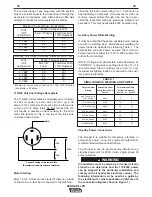
115/230 Volt Dual Voltage Receptacle
The 115/230 volt receptacle can supply up to 35 amps
of 230 volt power to a two wire circuit or up to 35
amps of 115 volt power from each side of a three wire
circuit (up to 70 amps total). Do Not connect the 115
volt circuits in parallel. Current sensing for the auto-
matic idle feature is only in one leg of the three wire
circuit as shown below.
Motor Starting
Most 1.5 HP motors can be started if there is no load
on the motor or other load connected to the machine,
Load from
115/230V
Dual Voltage Receptacle
0
1.1 KW
3.4 KW
5.7 KW
8.0 KW
Each 115V Duplex
20
20
20
20
0
Total from Both
115V Duplexes
40
40
40
20
0
K1616-1 Ranger 8 LPG
Maximum Current Draw - No Welding
Load from
115/230V
Dual Voltage Receptacle
0
1.1 KW
4.5 KW
5.7 KW
8.0 KW
Each 115V
Duplex
20
20
20
20
0
Total from Both
115V Duplexes
40*
40*
40*
20*
0
K1616-1 Ranger 8 LPG
Maximum Current Draw - No Welding - Machines with GFCI Kits
(Receptacle viewed from front of machine)
* Current Sensing for Automatic Idle
230V
115V*
115V
GND
since the full load current rating of a 1.5 HP motor is
approximately 20 amperes (10 amperes for 230 volt
motors). Larger motors through 2 hp can be run pro-
vided the receptacle rating as previously stated is not
exceeded. This may necessitate 230V operation only.
Auxiliary Power While Welding
It must be noted that the above auxiliary power ratings
are with no welding load. Simultaneous welding and
power loads are permitted by following Table I. The
permissible currents shown assume that current is
being drawn from either the 115V or 230V supply (not
both at the same time).
NOTE: Voltage and permissible watts decrease as
“CONTROL” is adjusted to settings less than 10. It is
recommended that at settings less than 10, only
incandescent lighting loads be connected to the auxil-
iary power receptacles.
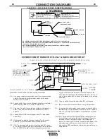
Standby Power Connections
The Ranger 8 is suitable for temporary, standby, or
emergency power using the engine manufacturer’s
recommended maintenance schedule.
The Ranger 8 can be permanently installed as a
standby power unit for 230V-3 wire, single phase 35
ampere service.
(Connections must be made by a licensed electri-
cian who can determine how the 115/230V power
can be adapted to the particular installation and
comply with all applicable electrical codes.) The
following information can be used as a guide by
the electrician for most applications (refer also to
the connection diagram shown in Figure 1.)
TABLE I
SIMULTANEOUS WELDING AND POWER
Output Selector
Permissible Power
Permissible Auxiliary
Setting
Watts (Unity Power
Current in Amperes
Factor)
@ 115V -or- @ 230V
Max. Stick or Wire
Feed Setting
None
0
0
175 Stick Setting
2100
18
9
125 Stick Setting
3800
32
16
90 Stick Setting
5000
42
21
70 Stick Setting
5600
48
24
50 Stick Setting
6300
54
27
NO WELDING
8000
70
35
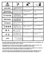
WARNING
Summary of Contents for RANGER 8 LPG
Page 32: ...NOTES RANGER 8 LPG ...
Page 33: ...NOTES RANGER 8 LPG ...
Page 34: ...NOTES RANGER 8 LPG ...

