background image

6

6

RANGER 8 LPG

INSTALLATION  INSTRUCTIONS

Safety Precautions

Machine Grounding

Because this portable engine driven welder or gener-
ator creates it’s own power, it is not necessary to con-
nect it’s frame to an earth ground, unless the
machine is connected to premises wiring (your home,
shop, etc.).

To prevent dangerous electric shock, other equip-
ment to which this engine driven welder supplies
power must:

a.

be grounded to the frame of the welder using a 
grounded type plug,

or

b.

be  double insulated.

When this welder is mounted on a truck or trailer, it’s
frame must be securely connected to the metal frame
of the vehicle.

Where this engine driven welder is connected to
premises wiring such as that in your home or shop, it’s
frame must be connected to the system earth ground.
See further connection instructions in the section enti-
tled “Standby Power Connections”, as well as the arti-
cle on grounding in the latest U.S. National Electrical
Code and the local code.

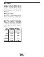
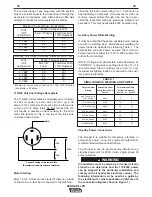
In general, if the machine is to be grounded, it should
be connected with a #8 or larger copper wire to a solid
earth ground such as a metal water pipe going into
the ground for at least ten feet and having no insulat-
ed joints, or to the metal framework of a building
which has been effectively grounded.  The U.S.
National Electrical Code lists a number of alternate
means of grounding electrical equipment.  A machine
grounding stud marked with the symbol        is provid-
ed on the front of the welder.
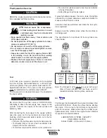
Spark Arrester

Some federal, state, or local laws may require that
gasoline engines be equipped with exhaust spark
arresters when they are operated in certain locations
where unarrested sparks may present a fire hazard.
The standard muffler included with this welder does
not qualify as a spark arrester.  When required by
local regulations, the K894-1 spark arrester must be
installed and properly maintained.

An incorrect arrester may lead to damage to the
engine or adversely affect performance.

Trailers

If the user adapts a non-Lincoln trailer, he must
assume responsibility that the method of attachment
and usage does not result in a safety hazard nor dam-
age the welding equipment.

Some of the factors to be considered are as follows:

1.  Design capacity of trailer vs. weight of Lincoln
equipment and likely additional attachments.

2.  Proper support of, and attachment to, the base of
the welding equipment so there will be no undue
stress to the framework.
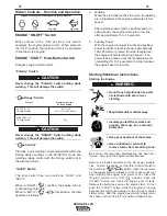
CAUTION

Do not attempt to use this equipment until you
have thoroughly read the engine manufacturer

s

manual supplied with your welder. It includes
important safety precautions, detailed engine
starting, operating and maintenance instructions,
and parts lists.

------------------------------------------------------------------------

ELECTRIC SHOCK can kill.

 Do not touch electrically live parts or

electrode with skin or wet clothing.

 Insulate yourself from work and

ground

 Always wear dry insulating gloves.

------------------------------------------------------------------------

ENGINE EXHAUST can kill.

 Use in open, well ventilated areas or

vent exhaust outside.

 The combustion of LPG fuel does pro-

duce carbon monoxide. Although the level

of CO emission is lower than gasoline combustion, the
exhaust from the Ranger 8 LPG can kill.

------------------------------------------------------------------------

MOVING PARTS can injure.

 Do not operate with doors open or

guards off.

 Stop engine before servicing.

 Keep away from moving parts.

------------------------------------------------------------------------

See additional warning information at

front of this operator

s manual.

-----------------------------------------------------------

WARNING

Summary of Contents for RANGER 8 LPG

Page 1: ...NUAL AND THE SAFETY PRECAUTIONS CONTAINED THROUGHOUT And most importantly think before you act and be careful RANGER 8 LPG For Machines with Code Number 10526 10541 10937 IM604 B August 2002 R Sales and Service through Subsidiaries and Distributors Worldwide Cleveland Ohio 44117 1199 U S A TEL 216 481 8100 FAX 216 486 1751 WEB SITE www lincolnelectric com World s Leader in Welding and Cutting Prod...

Page 2: ...R WEARERS SHOULD CONSULT WITH THEIR DOCTOR BEFORE OPERATING Read and understand the following safety highlights For additional safety information it is strongly recommended that you purchase a copy of Safety in Welding Cutting ANSI Standard Z49 1 from the American Welding Society P O Box 351040 Miami Florida 33135 or CSA Standard W117 2 1974 A Free copy of Arc Welding Safety booklet E205 is availa...

Page 3: ...rical earth ground 3 f Maintain the electrode holder work clamp welding cable and welding machine in good safe operating condition Replace damaged insulation 3 g Never dip the electrode in water for cooling 3 h Never simultaneously touch electrically hot parts of electrode holders connected to two welders because voltage between the two can be the total of the open circuit voltage of both welders ...

Page 4: ...event the welding sparks from starting a fire Remember that welding sparks and hot materials from welding can easily go through small cracks and openings to adjacent areas Avoid welding near hydraulic lines Have a fire extinguisher readily available 6 b Where compressed gases are to be used at the job site special precautions should be used to prevent hazardous situations Refer to Safety in Weldin...

Page 5: ...s et non inflamma bles 4 Des gouttes de laitier en fusion sont émises de l arc de soudage Se protéger avec des vêtements de protection libres de l huile tels que les gants en cuir chemise épaisse pantalons sans revers et chaussures montantes 5 Toujours porter des lunettes de sécurité dans la zone de soudage Utiliser des lunettes avec écrans lateraux dans les zones où l on pique le laitier 6 Eloign...

Page 6: ...where the information must be followed to avoid minor personal injury or damage to this equipment CAUTION Please Examine Carton and Equipment For Damage Immediately When this equipment is shipped title passes to the purchaser upon receipt by the carrier Consequently Claims for material damaged in shipment must be made by the purchaser against the transportation company at the time the shipment is ...

Page 7: ...TIG Welding Applications 10 OPERATING INSTRUCTIONS 10 15 Additional Safety Precautions 10 Welder Operation 10 Welder Output 10 Ranger 8 Typical Fuel Consumption 10 Welder Controls Function and Operation 11 Start Shutdown Instructions 11 Break in Period 12 Welding Process 12 Stick Constant Current Welding 12 TIG Constant Current Welding 12 Wire Feed Welding Processes Constant Voltage 13 Summary of ...

Page 8: ... Watt Incandescent Bulbs Can be Used for Standby Power OTHER FEATURES Polarity Switch for Selecting DC DC or AC Welding Output K930 1 TIG Module Available for high frequency and shielding gas control for AC and DC GTAW TIG welding applications Remote Control Receptacle Kit Available Electronic Engine Idler Engine Automatically Goes to Low Idle in 10 to 14 Seconds after Welding or Use of Auxiliary ...

Page 9: ...115V 35 Amps 230V Dimensions Weight 30 3 x 19 2 x 43 8 in 770 x 488 x 1113 mm 511 lbs 233 kg Ranger 8 LPG Kohler SPECIFICATIONS Ranger 8 Kohler CH20S Command w LP 2 Cylinder 4 Cycle Air Cooled LPG Engine Aluminum Alloy with Cast Iron Liners Electronic Ignition Auto Electronic Idler Overhead Valves 20 HP 3600 RPM Full Load 3500 RPM High Idle 3700 RPM Low Idle 2200 RPM 38 1 cu in 624 cc Fuel LPG cyl...

Page 10: ...150 200 250 0 10 20 30 40 50 60 70 80 DC STICK TIG CC OUTPUT OUTPUT AMPS OUTPUT VOLTS DC A 210 OUTPUT RANGE B 50 OUTPUT RANGE A B 0 50 100 150 200 250 300 350 0 10 20 30 40 50 60 70 80 CV OUTPUT RANGE 0 50 100 150 200 250 300 OUTPUT AMPS 350 0 5 10 15 20 25 30 35 40 DC WIRE FEED CV OUTPUT OUTPUT VOLTS DC SPECIFICATIONS ...

Page 11: ...electrode cable 25 ft 7 6m 3 AWG work cable headshield with No 12 filter GC300 work clamp and Cooltong 300 electrode holder Cables are rated at 225 amps 40 duty cycle Remote Control Receptacle Kit K892 1 Includes a 6 pin MS type Amphenol receptacle and a local remote toggle switch that mounts in the case front Requires a Remote Control Option Remote Control K857 Consists of a control box with 25 f...

Page 12: ...al TIG Module Docking Kit K939 1 Arc Start Switch K1814 Hand Amptrol K963 Foot Amptrol K870 Remote Control Receptacle Kit K892 1 WIRE FEED LN 25 K449 Includes internal contactor for across the arc operation no control cable Provides cold electrode until gun trigger is pressed Includes gas solenoid Remote control Receptacle Kit K892 1 and Remote Voltage Control Kit K444 1 are required for voltage c...

Page 13: ...d with exhaust spark arresters when they are operated in certain locations where unarrested sparks may present a fire hazard The standard muffler included with this welder does not qualify as a spark arrester When required by local regulations the K894 1 spark arrester must be installed and properly maintained An incorrect arrester may lead to damage to the engine or adversely affect performance T...

Page 14: ...T Specification 4E 240 The valve on the fuel cylinder must be installed on the outlet marked LIQUID The engine will not develop full power if connected to the vapor outlet Be certain that the cylinder valve is CLOSED before attempting to attach the fuel supply hose coupler to the cylinder Connect the coupler to the fuel cylinder and tighten by hand ___________________________________________ After...

Page 15: ...e connections should be checked periodically and tightened if neces sary Loose connections will result in overheating of the output studs When welding at a considerable distance from the welder be sure you use ample size welding cables Listed below are copper cable sizes recommended for the rated current and duty cycle Lengths stipulated are the distance from the welder to work and back to the wel...

Page 16: ...provide an unrestrict ed flow of clean cool air to the cooling air inlets and to avoid heated air coming out of the welder recirculating back to the cooling air inlet Connection of Lincoln Electric Wire Feeders Shut off welder before making any electrical connections Wire Feed Constant voltage Connection of the LN 25 to the Ranger 8 a Shut the welder off b Connect the electrode cable from the LN 2...

Page 17: ...tor Order Kit T12246 must be installed in the Ranger 8 OPERATING INSTRUCTIONS Additional Safety Precautions Always operate the welder with the roof and case sides in place as this provides maximum protection from moving parts and assures proper cooling air flow Do not tamper with the carburetor settings or the fuel hose from the regulator to the carburetor The engine has been pre set for optimum p...

Page 18: ...ne has started slowly return the choke control to the full in position Choke Open Do not touch electrically live parts of electrode with skin or wet clothing Keep flammable material away Insulate yourself from work and ground Wear eye ear and body protection Keep your head out of the fumes Use ventilation or exhaust to remove fumes from breathing zone WARNING 11 11 RANGER 8 LPG Welder Controls Fun...

Page 19: ... the Polarity switch to the desired polarity Set the RANGE switch to a setting that is equal to or slightly greater than the desired welding current The RANGE dial marking indicates the maximum current for that range Fine adjustment of the welding current is made by adjusting the output CONTROL or remote control For best arc stability use settings 5 through 10 The Ranger 8 can be used with a broad...

Page 20: ... WIRE FEED LN 25 WITH No AUTO Cold Press gun trigger LN 25 INTERNAL CONTACTOR contactor closes Welding starts immediately and engine goes to high idle NOTE Output Control must be set above 3 WIRE FEED LN 7 WITH Yes HIGH Cold Press gun trigger K240 CONTACTOR KIT contactor closes Welding starts immediately It is recommended that the Ranger 8 be used in HIGH idle when using the TIG Module It can be u...

Page 21: ...rough 2 hp can be run pro vided the receptacle rating as previously stated is not exceeded This may necessitate 230V operation only Auxiliary Power While Welding It must be noted that the above auxiliary power ratings are with no welding load Simultaneous welding and power loads are permitted by following Table I The permissible currents shown assume that current is being drawn from either the 115...

Page 22: ...ired length The 50 amp 115 230V plug is available in the optional plug kit 4 Plug this cable into the 50 amp 115 230V receptacle on the Ranger 8 case front Figure 1 CONNECTION OF RANGER 8 TO PREMISES WIRING 230 Volt 60 Hz 3 Wire Service POWER COMPANY METER 230 VOLT 115 VOLT 115 VOLT LOAD N NEUTRAL BUS GROUND PREMISES DISCONNECT AND SERVICE OVERCURRENT PROTECTION GND N NOTE No 8 COPPER CONDUCTOR CA...

Page 23: ... loading is recom mended for 100 fail safe operation DO NOT RUN THESE DEVICES WITHOUT ADDITIONAL RESISTIVE TYPE LOADS Inductive Single phase induction motors These devices may require large drills well pumps grinders small current inrush for starting refrigerators weed and hedge trimmers Some synchronous motors may be frequency sensitive to attain maximum output torque but they SHOULD BE SAFE from...

Page 24: ...r to the maintenance section of the Engine Owner s Manual for more information NOTE Engine life will be reduced if the oil and oil filter are not changed according to the manufacturer s recommendation 3 Air Cleaner With normal operating conditions the maintenance schedule for cleaning and re oil ing the foam pre filter is every 25 hours and replacement of the air cleaner filter every 100 hours Mor...

Page 25: ...r CHAMPION RC12YC Type 030 GAP GASES FROM BATTERY can explode Keep sparks flame and cigarettes away from battery To prevent EXPLOSION when INSTALLING A NEW BATTERY disconnect negative cable from old battery first and connect to new battery last CONNECTING A BATTERY CHARGER Remove bat tery from welder by disconnecting negative cable first then positive cable and battery clamp When rein stalling con...

Page 26: ...rcuit voltage on output studs 4 Faulty P C Board WHAT TO DO 1 Refer to wiring diagram check related leads 2 Refer to wiring diagram and check all related leads 200 224 200A 200B 201 201A 3 Lift brushes and check rotor resistance between slip rings It should be approximately 4 ohms 4 Replace with known good one 5 Disconnect lead 9 at D2 and check for continuity between leads 9 and 7 6 Replace with ...

Page 27: ... Low oil level 1 Air filter clogged 1 Spark plugs do not have specified gap 2 Spark plugs are fouled WHAT TO DO 1 Check for disconnected or broken leads in idler sensing circuit 2 Idler may not function with less than 100 to 150 watt load Set idler switch to high idle 3 Replace P C Board with known good one 1 Replace with known good one 2 Check the connection of the lead from the voltage regulator...

Page 28: ...OSS SUPPORT GROUND SCREW GND E GND E GND G 200B 219 201A 224 215 76 5E 75 77 J1 8 10 5D 7 254A 254 254 254A B 254A R1 OUTPUT CONTROL 75A 76A 77A 1 3 2 4 P5 J5 75A 77A 76A FIELD CAPACITOR AT BLOWER BAFFLE 209 211 U BLUE V VIOLET R R U V W ENGINE FOOT GND D GND C 5F 224A GND H TERMINALS 6 5 5L 115V 230V 5K GND D GND C J4 J3 J2 GND G 5 5L 5K 115V 115V 12 11 11 3E 3E 3C 3A 3A 3B 3B 3D 3D CB1 35A 35A C...

Page 29: ... 76 5E 75 77 J1 8 10 5D 7 254 B R1 OUTPUT CONTROL 75A 76A 77A 1 3 2 4 P5 J5 75A 77A 76A FIELD CAPACITOR AT BLOWER BAFFLE 209 211 R R U V W ENGINE FOOT GND D GND C 5F 224A GND H TERMINALS 6 5 5L 115V 230V 5K GND D GND C J4 J3 J2 GND G 5 5L 5K 115V 115V 12 11 11 3B 3B 3A 3A CB1 35A 35A CB2 CB3 20A 20A CB4 3 221 CAVITY 1 SILVER COLORED WHITE WIRES A CCW ALL CASE FRONT COMPONENTS SHOWN VIEWED FROM REA...

Page 30: ...rpose Connect it directly to the work piece independent of the welding work cable For conve nience this extended 21 lead should be taped to the welding work lead N G Tape up bolted connection where lead 21 is extended N H Idler switch on power source must be in high idle position N J If an optional remote output control is used connect it to this terminal strip or 6 pin Amphenol receptacle NOTE Te...

Page 31: ...1 9 31 M17215 4 CRM28731 9 09 9 09 UNDERCARRIAGE MOUNTING HOLES 42 25 42 00 CENTER OF GRAVITY WITH OIL IN ENGINE AND FULL FUEL TANK 11 31 FOR OIL FILTER REMOVAL 8 80 30 00 2 75 24 DIMENSION PRINT 24 RANGER 8 LPG DIMENSION PRINT Ranger 8 LPG Kohler ...

Page 32: ...NOTES RANGER 8 LPG ...

Page 33: ...NOTES RANGER 8 LPG ...

Page 34: ...NOTES RANGER 8 LPG ...

Page 35: ...TOTAL COST Now Available 12th Edition The Procedure Handbook of Arc Welding With over 500 000 copies of previous editions published since 1933 the Procedure Handbook is considered by many to be the Bible of the arc welding industry This printing will go fast so don t delay Place your order now using the coupon below The hardbound book contains over 750 pages of welding information techniques and p...

Page 36: ...electrically live parts or electrode with skin or wet clothing Insulate yourself from work and ground No toque las partes o los electrodos bajo carga con la piel o ropa moja da Aislese del trabajo y de la tierra Ne laissez ni la peau ni des vête ments mouillés entrer en contact avec des pièces sous tension Isolez vous du travail et de la terre Berühren Sie keine stromführenden Teile oder Elektrode...

Page 37: ...gute Be und Entlüftung des Arbeitsplatzes Mantenha seu rosto da fumaça Use ventilação e exhaustão para remover fumo da zona respiratória Turn power off before servicing Desconectar el cable de ali mentación de poder de la máquina antes de iniciar cualquier servicio Débranchez le courant avant l entre tien Strom vor Wartungsarbeiten abschalten Netzstrom völlig öff nen Maschine anhalten Não opere co...

Page 38: ...s and Service through Subsidiaries and Distributors Worldwide Cleveland Ohio 44117 1199 U S A TEL 216 481 8100 FAX 216 486 1751 WEB SITE www lincolnelectric com World s Leader in Welding and Cutting Products ...

Reviews: