


B-11
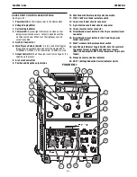
OPERATION
FLEXTEC
®
650x
Arc Link
This weld mode is intended to unlock basic non-synergic and
synergic modes intended for use with compatible ArcLink wire
feeders. All of the Flextec
®
650x user interface controls are
disabled in this mode and controlling the power source is accom-
plished from the wire feeder user interface.
Hot Start
– Not used for this welding process.
Arc Control
– Not used for this welding process.
Weld Terminals On/Remote
•
Not used for this welding process.
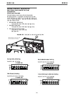
Amperage Display
– This display will display three dashed lines
when the machine is in the idle state. This indicates that
amperage is not settable in this weld mode. While output is
enabled, the actual welding amperage will be displayed. After
welding, the meter holds the actual amperage value for 5
seconds. Output adjustment while in the "hold" period results in
the "prior to operation" characteristics stated above. The displays
blink indicating that the machine is in the "Hold" period.
Voltage Display
– This display will display the pre-set welding
voltage when the machine is in the idle state. After welding, the
meter holds the actual voltage value for 5 seconds. Output
adjustment while in the "hold" period results in the "prior to
operation" characteristics stated above. The displays blink
indicating that the machine is in the "Hold" period.
Output Control Local/Remote
– Not used for this welding process
Output Control Dial
•
Not used for this welding process.
CrossLinc™
CrossLinc™ is a new welding system communication technology.
When using a CrossLinc™ enabled power source such as the
Flextec
®
650x and a CrossLinc™ enabled wire feeder such as the
LN-25X, welding voltage can be controlled remotely without the
use of an additional control cable.
The digital meters on the LN-25X will show the pre-set values for
wire feed speed and voltage prior to welding. During welding, the
meters will show actual current and voltage present at the wire
feeder. After welding the meters will then flash the last welding
current and voltage that was present during welding for 10-
seconds after welding. If WFS or voltage is adjusted during this 10
second period, the meters will go back to the pre-set value.
•
When a LN-25X enabled feeder is connected with the Flextec
®
650x using the standard weld power cable and the LN-25X
sense lead is attached to the work piece, the CrossLinc™
light will automatically illuminate on both the Flextec
®
650x
and the LN-25X. No additional pairing of the machine to the
feeder is needed. This light indicates the CrossLinc
connection is active and that control of the
Flextec
®
650x voltage can be made at the LN-25X feeder.
•
The Flextec
®
650x Weld Terminals On/Remote toggle should
be set to 'ON'. This powers the weld terminals for an across-
the-arc LN-25X wire feeder.
•
The Flextec
®
650x Output Control Local/Remote switch is
ignored once a CrossLinc peripheral is detected by the power
source.