


B-6
OPERATION
FLEXTEC
®
650x
INTERNAL CONTROLS - ENAbLING VRD,
mULTI-WELD AND CURRENT/VOLTAGE
CALIbRATION
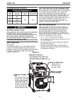
Internal Controls Description
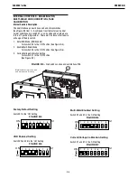
The User Interface pc board has one bank of dip switches
(See Figure B.3 Item 1). As shipped from the factory and under
normal conditions, dip switch #2 is ‘on’ position and all others are
in the ‘off’ position (Figure B.4). There are 3 instances that require
a change of the dip switch.
1. Enter VRD Mode (VRD Enabled)
Turn switch #5 to the ‘ON’ Position (See Figure B.5).
2. Enable Multi-Weld Mode
Turn switch #3 to the ‘ON’ Position (See Figure B.6).
3. Current/Voltage Calibration Setting
Turn switch #1 to the 'ON' Position
(See Figure B.7).
Factory Default Setting
Switch #2 in the ‘ON’ Setting
FIGURE B.4
VRD Enabled Setting
Switch #2 and #5 in the ‘ON’ Setting
FIGURE B.5
Multi-Weld Enabled Setting
Switch #2 and #3 in the ‘ON’ Setting
FIGURE B.6
Current/Voltage Calibration Setting
Switch #1 and #2 in the ‘ON’ Setting
FIGURE B.7
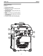
1
FIGURE B.3 -
Dip Switch Location on User Interface PCB
Machine back view - case side
and top removed for clarity
S1
ON
S1
1 2 3 4 5 6 7 8
S1
ON
S1
1 2 3 4 5 6 7 8
S1
ON
S1
1 2 3 4 5 6 7 8
S1
ON
S1
1 2 3 4 5 6 7 8