


A-9
INSTALLATION
FLEXTEC
TM
650
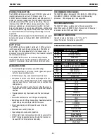
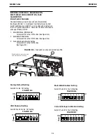
LN-10,DH-10 CONTROL SWITCH SETUP
Initial set up of the LN-10, DH-10 control for the system
components being used and for general operator preferences
is done using a pair of 8-pole DIP switches located inside the
LN-10, DH-10 control box.
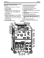
Setup DIP Switch Access
1) Shut off the input power to the LN-10, DH-10 control by
turning off the power at the welding power source it is
connected to.
2) Remove the two screws on the top of the LN-10, DH-10
control box door and swing the door down to open.
3) Locate the two 8-pole DIP switches, near the top left
corner of the LN-10, DH-10 Control P.C. board, labeled
S1 and S2.
4) Switch settings are only programmed during input
power-up restoration.
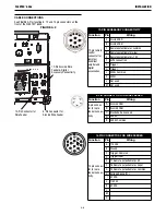
Setting the DIP Switches
The DIP switches are each labeled with an “ON” arrow
showing the on direction for each of the 8 individual switches
in each DIP switch (S1 and S2). The functions of these
switches are also labeled and set as described below:
Pwr Sources
S1
ON
S1
1 2 3 4 5 6 7 8
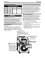
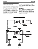
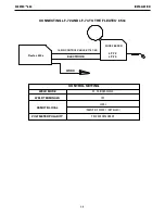
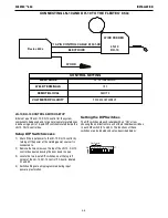
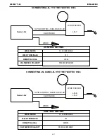
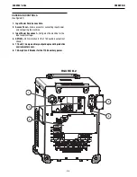
CONNECTING LN-10 AND DH-10 TO THE FLEXTEC
®
650x
CONTROL SETTING
14-PIN CONTROL CABLE K1501-XX
ELECTRODE
WIRE FEEDER
LN-10
DH-10
WORK
Flextec 650x
WELD MODE
WELD TERMINALS
REMOTE/LOCAL
VOLTMETER POLARITY
CV, CV-INNERSHIELD
OFF
REMOTE
PROCESS DEPENDENT