


B-4
OPERATION
FLEXTEC
®
650x
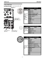
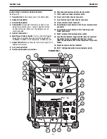
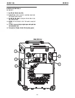
CASE FRONT CONTROL DESCRIPTIONS
(See Figure B.1)
1. Power Switch:
Controls input power to the Flextec 650x
2. Voltage Display Meter
3. Current Display Meter
4. Thermal LED:
A yellow light that comes on when an over
temperature situation occurs. Output is disabled until the
machine cools down. When cool, the light goes out and
output is enabled.
5. Hot Start Control Dial
6. Weld Process Selector Switch:
A rotary switch that toggles
through the six available weld modes for the Flextec 650X –
CC-SMAW; CC-GTAW; CV; CV-Innershield; CV-SAW; Arc Link
7. Output Control Dial:
Sets the output current or voltage for the
selected weld process.
8. Arc Force Control Dial
9. Positive and Negative output studs
10. Wire Feeder Voltmeter polarity selection switch
11. 115V or 42V wire feeder selector switch
12. 14-pin wire feeder circular connector
13. 5-pin ArcLink wire feeder circular connector
14. 12-pin remote circular connector
15. Circuit breaker reset button for the 12-pin remote circular
connector
16. Circuit breaker reset button for the 5 and 14-pin wire
feeder connectors
17. Weld Terminals On/Remote selector switch
18. Local/Remote Selector Toggle Switch: Sets the control of
the output to local (output control knob) or remote
(K857-2 hand amptrol, K870-2 foot amptrol or 14-pin wire
feeder)
19. CrossLinc communication indicator
20. VRD
™
(Voltage Reduction Device) Indicator Lights
1
18
17
15
16
14
13
12
11
10
9
7
5
6
4
3
2
8
19
20
FIGURE B.1