background image

APPENDIX A

65

Function

Operation

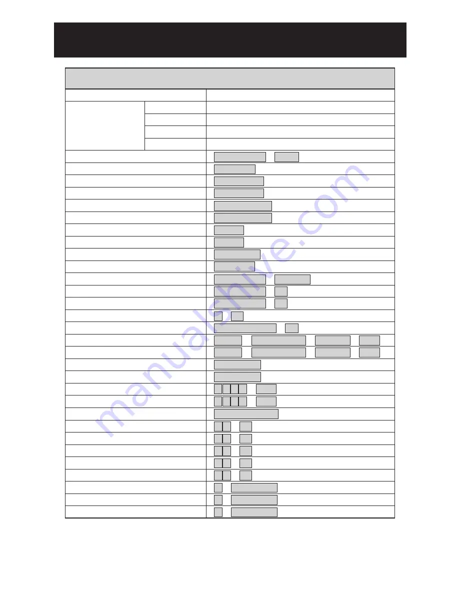
Quick Reference Table

Pan / Tilt Control

To Tilt Up

Dome Selection

To Tilt Down

To Pan Left

To Pan Right

Zoom In

Zoom Out

Manually Bring The Object Farther

Manually Bring The Object Closer

Auto Focus

Open Iris

Close Iris

Auto Iris

180  Horizontal Instant Flip

Set or Recall Preset Position

Set Preset Speed

Set Preset Dwell

Store Preset Data

Set Preset Group

Activate Auto Pan

Stop Auto Pan

Delete 128 Preset position Data

Reset Alarm

Select Return Time

Select Return Mode

Select Auto Mode

Reboot System

Activate Patrol Learn Mode

Stop patrol Learn Mode

Stop Password

Activate Password

Edit Password

Single Preset Position Delete

 Numeric Key  +  CAM

 ZOOM IN

 ZOOM OUT

 FOCUS FAR

 FOCUS NEAR

 AUTO FOCUS

 IRIS O

 IRIS C

 AUTO IRIS

 180  REV

 Numeric Key  +  PRESET

 Numeric Key  +  F1

 Numeric Key  +  F2

 1  +  F3

 5  1  +  F4

 5  2  +  F4

 5  3  +  F4

 5  4  +  F4

 5  5  +  F4

 1  +  KEY LOCK

 2  +  KEY LOCK

 3  +  KEY LOCK

 SHIFT  +  Numeric Keys  +  PRESET  +  ENT

 SHIFT  +  Numeric Keys  +  PRESET  +  CLR

 Numeric 1,2,3,4  +  F4

 AUTO PAN

 AUTO PAN

 9  0  1  1  +  CLR

 9  0  1  3  +  CLR

 ALARM RESET

Push Joystick Forward

Push Joystick Down

Push Joystick Left

Push Joystick Right

 (Auto Focus LED off)

 (Auto Focus LED off)

 (Auto Focus LED on)

 (Auto Iris LED off)

 (Auto Iris LED off)

 (Auto Iris LED on)

 (128 preset position)

 (1  ~ 255 /sec)

 (0 ~ 255 sec)

 (4 Group)

 (Auto Pan LED on)

 (Auto Pan LED off)

Single Preset Position Saving

Summary of Contents for IPS 8264

Page 1: ...E OUTDOOR D N WDR 700TVL FAST DOME CAMERA SP8264 8268 N P SP8364 8368 N P IPS8264 8268 N P IPS8364 8368 N P OUTDOOR D N WDR 700TVL FAST DOME IP CAMERA ST8264 8268 N P ST8364 8368 N P OUTDOOR HUMAN TRACKING FAST DOME CAMERA ...

Page 2: ...eyboard Fast Dome with PC Control Fast Dome DVR and Keyboard Fast Dome IP Camera with PC Control Operation Initial Power Up Inspection Manual Operation Pan Tilt Control Fast Dome Selection Zoom Lens Control Focus Control Iris Control Horizontal 180 Instant Flip Preset Positions Setting Recalling Preset Positions Setting Preset Group Changing Preset Data Activating Auto Pan Deleting Preset Data Reb...

Page 3: ...de Setting Auto Scan Mode Setting Patrol Mode Setting Preset Function Setting Menu Tour Function Setting Menu Privacy Zones Setting Menu Alarms Setting Menu Password Function Menu IP Camera not Support Restore Factory Defaults Schedule Setup Menu Alarm Input Schedule Setting Menu Startup Auto Options Menu Daylight Saving Time Menu Specification Operational Camera Optical Lens Electrical Environmen...

Page 4: ...nufacturer s control systems Outdoor D N WDR 700TVL LILIN s Outdoor Fast Dome series are fully functional and user friendly It will meet your need for a wide range of surveillance applications The application for LILIN tracking dome are 1 Access control area Bank Chest Military Magazine Oil or Chemical tank 2 After hour monitoring area Warehouse Archives Parking exit 3 Educational Institution or V...

Page 5: ...ter In Color Out Mono Auto Switch from color to mono when light drops below 3 lux Schedule Switch from color to mono by time setup 2 650 TV Lines Color 700 TV Lines Mono 3 0 1Lux Color 0 05Lux Mono 4 On Screen Setup Menu 5 White Balance Control Auto Tracking Auto Correction Manual 2 Anti Color Rolling 6 Wide Dynamic Range On 60dB Off 7 Back Light Compensation On Off 8 Auto Gain Control 0dB 37dB 9 ...

Page 6: ...The position of moving object is near the center of FOV and its size is approximately smaller than 1 6 of FOV Zoom Out The size of moving object is approximately larger than 1 6 of FOV The position of moving object at the outside of FOV on the other hand the moving object almost moving out of FOV 6 Human Tracking Fast Dome Camera series uses the home position of auto tracking mode 7 The auto track...

Page 7: ... cable and change the cable if there is damage on cable Violation may cause short circuit fire and injury 10 Make sure ground is well connected to avoid damage caused by lightning 11 Do not put any foreign objects inside the equipment and do not spray any liquid on equipment This will avoid short circuit damage 12 Do not touch power connection with wet hands to avoid short circuit or electricity s...

Page 8: ...Dome Cover Camera Case Upper Base Power In Jack AC100 240V Power In Jack AC24V RS 485 In Out Terminal Video Out Jack Alarm In Out connector RJ45 Network Connector IPS826X 836X STRUCTURAL ELEMENT 7 ...

Page 9: ...or ON OFF 2 wiring system HALF duplex or 4 wiring system Full duplex Transmission speed selection 1 Transmission speed selection 2 Protocol selection 1 Protocol selection 2 Protocol selection 3 Protocol selection 4 NA RS 485 In Out Terminal Resistor Setting Daisy Connection Set RS 485 In and Out terminal resistor as ON Factory Initialize Parallel Connection Set the front and last equipments termin...

Page 10: ...ITLILIN PROTOCOL 2 is the new protocol for controlling fast dome cameras The protocol contains 7 bytes which include a check sum byte and extra control codes The check sum byte for example can prevent RS 485 interference affecting a protocol The extra control codes for example can provide the feature of controlling absolute position of a fast dome camera Please refer to MERIT LILIN PROTOCOL2 MLP2 ...

Page 11: ...6 7 5 4 3 2 ON 7 6 8 1 1 1 7 6 8 5 4 3 2 2 3 4 5 ON 8 6 7 5 4 3 2 7 6 8 ON 1 2 3 4 5 8 9 9 9 9 9 9 9 9 9 9 9 9 9 9 9 9 0 0 0 0 0 0 0 0 0 0 0 0 0 0 0 0 6 7 ON ON 1 2 3 4 5 8 6 7 1 1 5 4 3 2 7 6 8 ON 5 4 3 2 ON 7 6 8 1 1 ON 2 3 4 5 8 6 7 ON 5 4 3 2 ON 7 6 8 1 1 1 8 6 7 2 3 4 5 2 3 4 5 ON 8 6 7 5 4 3 2 7 6 8 ON 1 1 5 4 3 2 7 6 8 ON 2 3 4 5 ON 8 6 7 1 1 ON 2 3 4 5 ON 8 6 7 5 4 3 2 ON 7 6 8 1 1 1 7 6 8...

Page 12: ... 2 7 6 8 9 10 ON 1 5 4 3 2 7 6 8 9 10 ON 1 5 4 3 2 7 6 8 9 10 ON 1 5 4 3 2 7 6 8 9 10 ON 1 5 4 3 2 7 6 8 9 10 ON 1 5 4 3 2 7 6 8 9 10 ON 1 5 4 3 2 7 6 8 9 10 ON 1 5 4 3 2 7 6 8 9 10 ON 1 5 4 3 2 7 6 8 9 10 ON 1 5 4 3 2 7 6 8 9 10 ON 1 5 4 3 2 7 6 8 9 10 ON 1 5 4 3 2 7 6 8 9 10 ON 1 5 4 3 2 7 6 8 9 10 ON 1 5 4 3 2 7 6 8 9 10 ON 1 5 4 3 2 7 6 8 9 10 ON 1 5 4 3 2 7 6 8 9 10 ON 1 5 4 3 2 7 6 8 9 10 ON...

Page 13: ...4 3 2 7 6 8 9 10 ON 1 5 4 3 2 7 6 8 9 10 ON 1 5 4 3 2 7 6 8 9 10 ON 1 5 4 3 2 7 6 8 9 10 ON 1 5 4 3 2 7 6 8 9 10 ON 1 5 4 3 2 7 6 8 9 10 ON 1 5 4 3 2 7 6 8 9 10 ON 1 5 4 3 2 7 6 8 9 10 ON 1 5 4 3 2 7 6 8 9 10 ON 1 5 4 3 2 7 6 8 9 10 ON 1 5 4 3 2 7 6 8 9 10 ON 1 5 4 3 2 7 6 8 9 10 ON 1 5 4 3 2 7 6 8 9 10 ON 1 5 4 3 2 7 6 8 9 10 ON 1 5 4 3 2 7 6 8 9 10 ON 1 5 4 3 2 7 6 8 9 10 ON 1 5 4 3 2 7 6 8 9 10...

Page 14: ...6 8 9 10 ON 1 5 4 3 2 7 6 8 9 10 ON 1 5 4 3 2 7 6 8 9 10 ON 1 5 4 3 2 7 6 8 9 10 ON 1 5 4 3 2 7 6 8 9 10 ON 1 5 4 3 2 7 6 8 9 10 ON 1 5 4 3 2 7 6 8 9 10 ON 1 5 4 3 2 7 6 8 9 10 ON 1 5 4 3 2 7 6 8 9 10 ON 1 5 4 3 2 7 6 8 9 10 ON 1 5 4 3 2 7 6 8 9 10 ON 1 5 4 3 2 7 6 8 9 10 ON 1 5 4 3 2 7 6 8 9 10 ON 1 5 4 3 2 7 6 8 9 10 ON 1 5 4 3 2 7 6 8 9 10 ON 1 5 4 3 2 7 6 8 9 10 ON 1 5 4 3 2 7 6 8 9 10 ON 1 5 ...

Page 15: ...ome Connection Jack and Cable Requirement Copper Wire AWG Length of Cable approx m ft 24 2 0 22mm 20 65 22 2 0 33mm 30 100 20 2 0 52mm 45 160 18 2 0 83mm 75 260 Accessory Connector Information Assemble the Cable with the Accessory Connector a Strip back the cable jacket approx 3mm and separate the individual conductors 3mm Insert Contact UP Electrical Wire PIN 1 2 3 4 Power AC24V Live Black AC24V ...

Page 16: ...st dome through twisted pair cable Transmission Distance Max 1 Kilometer 4 Video Out BNC Jack Video Signal Output CVBS 1 0Vp p 75 BNC Recommended Data Cable 5C2V 5 Alarm In Out Connector Each fast dome contains 6 alarm inputs and 1 alarm output Alarm Input Voltage 5 6V max Alarm Output 1A 24VDC Recommended Data Cable UL26 AWG 80 300V UL24 AWG 80 C 300V 6 Network Connector RJ45 IPS8364 8368 LAN 10 ...

Page 17: ...er must prepare their own screws Step 2 Fix base of bracket on the wall If this circle hole is utilized please use this tool to knock at this circle hole Untighten two screws from iron slice of fixed cable in the bracket and then pick off the iron slice Attach outdoor fast dome camera to bracket and tighten three screws Put output cables of outdoor fast dome camera in sequence through tube of brac...

Page 18: ... Fast Dome Camera Setting Attach the dome cover to camera case Tighten three screws to fix the dome cover Step 5 Connect Jack Attach outdoor fast dome camera including bracket to base of bracket Connect video cable Connect RS 485 cable Connect alarm out input cable After connecting all of cables put all of cables and jacks in the tube of bracket Put iron slice of fixed cable on the bracket and tig...

Page 19: ...use cable Step 6 Fix bracket and outdoor fast dome camera with base Step 2 To install fast dome camera Untighten three screws from upper base Turn the camera case counter clockwise Separate the camera case from upper base Attach camera case to upper base Turn the camera case clockwise to tight position Tighten three screws to upper base to fix the camera case To take the camera case into the hole ...

Page 20: ...iplexer or quad or switcher RS 485 Connection 7th pin TXDI of Connector Box connects to TXDI of RS 485 jack on fast dome 8th pin TXDI of Connector Box connects to TXDI of RS 485 jack on fast dome SYSTEM CONFIGURATION DVR Quad Switcher OR VIDEO OUT VIDEO OUT OUT VIDEO VIDEO OUT IN VIDEO IN VIDEO IN VIDEO RS 485 IN VIDEO IN VIDEO IN VIDEO AC 24VAC 100 240VAC Monitor Monitor Monitor PIH 208AL MULTIFU...

Page 21: ...TXDO of 1st fast dome connects to TXDI of 2nd dome and TXDO of 1st dome to TXDI of 2nd dome RS 485 Connection Between PIH 804 Data Distributor and Keyboard 7th pin TXDI of Connector Box connects to TXDO on RS 485 OUT jack of PIH 804 8th pin TXDI of Connector Box connects to TXDO on RS 485 OUT jack of PIH 804 Ⅲ Ⅲ Ⅲ Ⅲ Ⅲ Ⅲ Multiplexer RS 485 ADAPTOR AC RS 485 DATA CONTROL CHAIN 1 CHAIN 2 CONTROL CHAI...

Page 22: ...s to TXDI of 2nd dome and TXDO of 1st dome to TXDI of 2nd dome 64 fast dome can be linked through the connection as shown RS 485 Connection Between Keyboards 5th pin TXDO of 1st keyboard s connector box connects to 7th pin TXDI of 2nd keyboard s connector box 6th pin TXDO of 1st keyboard s connector box connects to 8th pin TXDI of 2nd keyboard s connector box RS 485 Connection Between Keyboard and...

Page 23: ...format format N 8 1 Baud Rate 9600 bps The PC control port RS 232 is converted to RS 485 format by interface User may use their own software protocol or software provided by LILIN to control the dome In this system up to 64 fast domes can be linked VIDEO FAST AC PC RS 232 OUT RS 485 Interface RS 232 RS 485 IN VIDEO DOME 1 AC FAST DOME 2 DOME 3 FAST AC OUT VIDEO VIDEO OUT RS 485 RS 485 NEXT DOME VI...

Page 24: ...R and Keyboard The DVR System is an advanced digital recording product with long recording time and easy searching features Telemetry remote control is twisted pair for data transmission to the fast dome Fast Dome can be controlled directly from the control panel of the DVR or from keyboard Each DVR Digital Video Recorder can manage 16 video signals and via RS 485 ot daisy connection 16 sets of fa...

Page 25: ...mera with PC Control PC AC VIDEO OUT VIDEO IN 24Vac 100 240Vac Monitor Internet Ethernet Ethernet cable Next Dome ADAPTOR Keyboard Controller 1 8 2 7 3 6 4 5 AC GND DC12V TXDI TXDI TXDO TXDO GND RS 485 RS 485 RS 485 Connection 7th pin TXDI of RS 485 jack at back of the keyboard connects to TXDI of RS 485 jack on fast dome 8th pin TXDI of RS 485 jack at back of the keyboard connects to TXDI of RS 4...

Page 26: ...will remain in Auto Scan until an operator cancels it For setting Fast Dome IP Camera other features or functions please refer to IP instruction manual Manual Operation Pan Tilt Control To control the pan and tilt movement of the dome simply use the joystick on the keyboard to pan the camera left push the joystick to the left to tilt down pull the joystick down towards you To move the dome faster ...

Page 27: ...ome farther Focusing will stop when the key is released 2 Manual focus near Push key The target will become nearer Focusing will stop when the key is released 3 Auto Focus Push key The lens will automatically adjust itself for optimum focus 1 2 3 4 5 6 7 8 9 0 CLR ENT FOCUS FAR ALARM RESET F1 F2 F3 F4 ESC SET DVR MATRIX MON PRESET SEARCH CTRL2 180 SEQ FOCUS NEAR AUTO PAN SHIFT AUTO FOCUS AUTO IRIS...

Page 28: ...tions Each preset stores the exact position of the camera and automatic pan tilt zoom focus and iris setting Once the data is set the preset can be recalled for viewing or the presets can be set for auto pan Only the first 16 preset positions of fast dome can be set to auto pan mode and first 6 preset positions are corresponding with the 6 alarm inputs Selecting Fast Dome Push key followed by key ...

Page 29: ...have been completed the information must be stored or it will not be memorized by the system Push key followed by key two beeps will be heard confirming that data is stored Note For the first 16 presets on each dome the above steps must be repeated For presets 17 128 there is a default speed and dwell setting so steps 5 and 6 are not required 7 1 2 3 4 5 6 7 8 9 0 CLR ENT FOCUS FAR ALARM RESET F1 ...

Page 30: ...14th 15th and 16th preset positions To set up group 1 Push key followed by key Ex To set Group 1 To set Group 2 3 To set Group 3 4 To set Group 1 2 3 To set Group 2 3 4 To set Group 1 2 3 4 1 2 3 4 5 6 7 Changing Preset Data In order to change any preset position from the one stored the dome must first be sent to that preset position To change the 4th preset position of the Dome number 3 perform t...

Page 31: ...essing key followed by the key All 128 preset data will be erased Push followed by key 1 2 3 4 5 6 7 8 9 0 CLR ENT FOCUS FAR ALARM RESET F1 F2 F3 F4 ESC SET DVR MATRIX MON PRESET SEARCH CTRL2 180 SEQ FOCUS NEAR AUTO PAN SHIFT AUTO FOCUS AUTO IRIS CTRL1 C SET SPRAY ICR LIGHT C ESC CAM WIPER LENS AUTO PAN AUTO PAN CAM 2 CAM 1 2 3 4 5 6 7 8 9 0 CLR ENT FOCUS FAR ALARM RESET F1 F2 F3 F4 ESC SET DVR MA...

Page 32: ...set positions When an alarm signal is triggered the dome will go to the relevant position at 360 sec Make sure the first 6 preset positions are set to desired alarm areas Alarm input can be set to NC normally close or NO normally open depends on alarm detector Relationship Between Alarm Inputs and First 6 Presets Alarm Input 1 will send the dome to Preset Position 1 Alarm Input 2 will send the dom...

Page 33: ... LEVEL ADVANCED SETTING EXPOSURE MODE AUTO INT DIGITAL EFFECT CONTRAST SHARPNESS HUB R GAIN B GAIN CONTRAST 3D NR E ZOOM DIS AUTO HLC ATW DAY NIGHT ADJUST B GAIN B GAIN SPEED NIGHT DAY PRESET R GAIN R GAIN DELAY CNT ATW FRAME ENVIRONMNT MANUAL SCHED DAY NIGHT LL IR LIGHT NORMAL CLIP LEVEL SCALE AWC USER1 USER2 ANTICR WHITE BAL HLC DAY NIGHT NIGHT ENV SYNC IMAGE ON OFF AUTO ONE PUSH HIGH LUM MODE L...

Page 34: ...ION EXIT REBOOT SYSTEM BACK STARTUP AUTO OPTIONS DAYLIGHT SAVING TIME ALARM IN END START STARTUP 1 HH MM STARTUP 2 HH MM 1 START 2 END 3 START 4 END 5 START 6 END 3 HH MM 4 HH MM 5 HH MM 6 HH MM 7 HH MM 8 HH MM PRESETS PRESET NUMBER PRESET MAP EDIT POSITION EDIT ID SCENE FILES DWELL TIME SPEED CLR PRESET ON EXPOSURE MODE WHITE BALANCE PAN TILT HOME POSITION SELF RETURN TIME SELF RETURN MODE AUTO M...

Page 35: ... to recall Setup Menu Press key to exit setup menu or push joystick down to select EXIT and then press key to exit setup menu Language Selection Press key into Setup Menu Push joystick down to select LANGUAGE and then push joystick left or right to select language Press key to exit setup menu or push joystick down to select EXIT and then press key to exit setup menu Fast Dome Camera Function Setup...

Page 36: ...cter Setup Menu Press key into Setup Menu Push joystick down to select DISPLAY SETUP and then press key to display character setup menu Push joystick down to select BACK and then press key to go back or push joystick down to select EXIT and then press key to exit setup menu 1 Display Character Setup Menu C SET CTRL1 C SET CTRL1 C SET CTRL1 C SET CTRL1 C SET CTRL1 C SET CTRL1 C SET CTRL1 C SET CTRL...

Page 37: ... elapsed time stops when Alarm Input is triggered 5 10 15 20 25 30sec can be selected 4 Alarm Message Setting Push joystick down to select DATE TIME and then push joystick left or right to make selection OFF No Date Time on the monitor screen ON Display Date Time on the monitor screen When selection is open and then press key date time will be set 5 Date and Time Setting C SET CTRL1 DATE TIME TIME...

Page 38: ...ed in the place of the direction indicators if desired The direction indicators are N north NE northeast E east SE south east S south SW southwest W west and NW northwest Push joystick down to select AREA TITLE and then push joystick left or right to select area title setup OFF Turn off display of area title direction indicators and text NESW Displays direction indicators Select NESW and pressing ...

Page 39: ...elect character and press key to confirm The character selected will be showed in edit area If you need space push joystick down to select SPACE and press key to confirm Press or to switch to next character list Repeat all steps to complete Area Title 2 Copy Area Title to Another Area Push joystick down to select EDIT AREA and push joystick left or right to select first copy of characters Push joy...

Page 40: ...UM or ALL Then press key to confirm ABOVE NUM Only clear character of allotted area ALL Clear character off all area C SET CTRL1 8 Character Location 2012 01 01 00 00 01 CAM 001 Outdoor Alarm Message Input 1 350deg 90deg 1 0x Date Time Preset ID Auto Pan Alarm Message Horizontal Angle Zoom Ratio Vertical Angle Display Dome Function Setup Menu Press key into Setup Menu Push joystick down to select ...

Page 41: ...e Push focus with the target image 2 Zoom Speed Setting Push joystick down to select ZOOM SPEED and then push joystick left or right to adjust zoom speed setting Zoom speed ranges are 00 07 3 Focus Speed Setting Push joystick down to select FOCUS SPEED and then push joystick left or right to adjust focus speed setting 4 Auto Iris Setting Push joystick down to select AUTO IRIS LEVEL and then push j...

Page 42: ...SHUT 40 AGC 25dB x0 50 OFF 1 2 1 AGC Auto Gain Control GAIN Push joystick down to select GAIN and then push joystick left or right to make selection Gain Control ranges are 20dB 36dB SHUT No adjustment when in AGC mode 1 2 2 SLOW Slow Shutter Mode GAIN No adjustment when in SLOW mode SHUT Push joystick down to select SHUT and then push joystick left or right to make selection Shut control ranges a...

Page 43: ...il and overexposure improve Push joystick down to select ATR EX CONTRAST and then push joystick left or right to make selection Note The ATR EX function setting is available only when high luminance mode is set to wide dynamic range HIGH LUM MODE WDR SHUT 1 3 BLC Setting AUTO SETUP HIGH LUM MODE BRIGHTNESS LOW LUM MODE GAIN SHUT BRIGHTNESS ATR EX CONTRAST BACK EXIT WDR SHUT 99 AGC 25dB MID LOW MID...

Page 44: ...lance suitable for 1800 10500K color temperature environment 1 1 SPEED Push joystick down to select SPEED and then push joystick left or right to make selection ATW speed ranges are 0 255 fast slow 1 ATW Auto Trace White Balance SETUP 43 This mode can set a fixed WDR and shutter speed with iris to exhibit image effect Push joystick down to select SHUT and then push joystick left or right to make s...

Page 45: ... or right to adjust white balance to lower color temperature and push joystick down to select B GAIN and then push joystick left or right to adjust white balance to higher color temperature Confirm color temperature and then press key to record data in the memory 4 USER2 Manual White Balance mode 2 suitable for 1800 10500K color temperature environment Select USER2 and press key into USER2 WB adju...

Page 46: ... NIGHT and then push joystick left or right to select mode 4 Day Night Setting AUTO SCHED DAY NIGHT 45 This mode suppresses the color rolling which arises when there are slight deviations between blinking frequency of non inverter fluorescent lights and the drive frequency of the image sensor devices 5 ANTICR C SET CTRL1 C SET CTRL1 C SET CTRL1 C SET CTRL1 C SET CTRL1 produce color image When ligh...

Page 47: ...ress key into time C SET CTRL1 C SET CTRL1 Push joystick down to select SYNC and then move joystick left or right to select INT mode or LL mode INT Use synchronization signal of internal camera LL Synchronize synchronization signal of camera and AC signal of external power 6 Synchronization Mode Setting ADVANCED SETTING SHUTTER AGC WHITE BAL HLC DAY NIGHT NIGHT ENV SYNC IMAGE BACK EXIT MANUAL ATW ...

Page 48: ...joystick left or right to adjust contrast setting Contrast control ranges are 0 255 3 SHARPNESS Push joystick down to select SHARPNESS and then push joystick left or right to adjust sharpness setting Sharpness control ranges are 0 15 4 HUE Push joystick down to select HUE and then push joystick left or right to adjust hue setting HUE control ranges are 0 100 2 CONTRAST 47 Able to control Red Gain ...

Page 49: ...izer Push joystick down to select DIS and then push joystick left or right to select ON or OFF mode Note If a camera shake or vibrate and the DIS is set to ON it will continue to show stable image or vibration is reduced 8 E ZOOM Pan Tilt Setting Menu After getting in dome setting menu push joystick down to select PAN TILT and then press key into pan tilt setting menu 1 Display the Pan Tilt Settin...

Page 50: ...nctions are only for tracking models ST826X 836X Note When keyboard control isn t used and Return Time is also over Return Mode function will be started 4 Self Return Mode Setting OFF HOME SCAN SEQ TOUR1 TOUR2 PATROL TRACK Push joystick down to select AUTO MODE and then push joystick left or right to select mode OFF NO action SCAN Perform auto scan mode SEQ Perform preset group mode TOUR1 Perform ...

Page 51: ...etting menu 7 Patrol Mode Setting PATROL LEARN CLEAR BACK EXIT C SET CTRL1 1 Position of Auto Pan Setting Push joystick down to select EDIT POSITION and then press key into setting menu Push joystick left right up or down to select start position and then press to adjust zoom focus iris then press key to confirm Push joystick left or right to select end position and then press key to confirm C SET...

Page 52: ...SET NUMBER and then push joystick left or right to select preset number 1 128 2 Select number by PRESET MAP Push joystick down to select PRESET MAP and then press key into preset map Push joystick left right up or down to select preset number and then press key into preset setting menu If need to select preset numbers 33 64 push joystick down to 33 64 and then press key into preset numbers 33 64 2...

Page 53: ...acter list Repeat all steps to complete preset ID 2 Copy preset ID to Another Preset Push joystick down to select EDIT AREA and push joystick left or right to select first copy of characters Push joystick down to COPY and press key to confirm At this time first character of preset ID will be copy to first character position of another preset ID and press key to do next copy Push joystick down to O...

Page 54: ... C SET CTRL1 Push joystick down to select DWELL TIME and then push joystick left or right to select needful dwell time 1 255 sec Note Only preset No 1 16 can set dwell time because group of auto pan can only edit preset No 1 16 Other preset numbers can t set dwell time 6 Dwell Time Setting Push joystick down to select SPEED and then push joystick left or right to select speed of preset 1 255 deg s...

Page 55: ... presets Push joystick left or right to select preset 1 128 Press key to confirm and push joystick to select BACK then press key again to back to tours setting or push joystick to select EXIT and press key to exit setting menu 3 Edit Tour Push joystick down to select CLEAR ABOVE NUMBER and then press key to cancel tour 4 Cancel Tour Push joystick down to select DWELL TIME and then push joystick le...

Page 56: ...al zoom lens and auto focus lens and then press key to confirm and get into privacy zone mask area for editing Press key and then push joystick left right up or down to extend privacy zone mask area Press key and then push joystick left right up or down to reduce privacy zone mask area After completing setting press key to confirm and back to privacy zones setting menu Note Optical lens can just a...

Page 57: ...y open If contact is short alarm will be triggered NC mode Contact of input alarm is normally short If contact is open alarm will be triggered 3 Input of Alarm Mode Setting OFF NO action POSI Alarm corresponding preset positions mode SCAN Perform auto scan mode SEQ Perform preset group mode TOUR1 Perform tour1 list mode TOUR2 Perform tour2 list mode PATROL Perform memory patrol mode TRACK Perform ...

Page 58: ...ush joystick down to select EDIT PASSWORD and then press key into edit password setting Push joystick left or right to select number 1 9 and then press key to confirm The number that is selected will be displayed on the edit column Repeat above steps until password setting has been completed 3 Edit Password Setting C SET CTRL1 C SET CTRL1 C SET CTRL1 Fast Dome IP Camera not support OFF IN 1 IN 2 I...

Page 59: ...evious passwords have to enter on the setting menu first and then do modifying password 4 Modify Password C SET CTRL1 C SET CTRL1 After password function is ON press key to display frame of input password on the screen When protocol is MLP1 push joystick up or down to select number 0 9 and press key to confirm Select numbers will become to Repeat above steps until passwords have been completed If ...

Page 60: ...actory initialization for all Note PLEASE WAITING FACTORY INITIALIZATION will show on the screen after confirmation 2 Factory Initial for All C SET CTRL1 C SET CTRL1 C SET CTRL1 PLEASE WAITING FACTORY INITIALIZATION Push joystick down to select RESTORE and then push joystick left or right to select CAMERA Press key to confirm and Are you sure continue will display on the screen Press key again and...

Page 61: ...Setting Menu ALARM IN STARTUP START END BACK EXIT OFF 00 00 00 00 Push joystick down to select STARTUP and then push joystick left or right to select ON or OFF OFF Alarm input schedule function is OFF alarm input trigger will not be limited by schedule time ON Alarm input schedule function is ON alarm input trigger will be limited by schedule time 2 Start Alarm Input Schedule Setting Push joystick...

Page 62: ...00 01 00 01 00 2 Schedule Time Setting Push joystick down to item 1 to 8 and complete time setting and then get into auto setting Then push joystick left or right to select auto mode and press key to confirm OFF NO action STOP Stop the auto mode SCAN Perform auto scan mode SEQ Perform preset group mode TOUR1 Perform tour1 list mode TOUR2 Perform tour2 list mode PATROL Perform memory patrol mode TR...

Page 63: ...isplay the Daylight Saving Time Setting Menu DAYLIGHT SAVING TIME STARTUP 1 START 2 END 3 START 4 END 5 START 6 END BACK EXIT Push joystick down to select STARTUP and then push joystick left or right to select ON or OFF 2 Start Daylight Saving Time Function Setting Push joystick down to select START and press key into setting mode and then push joystick left or right to select start time Then pres...

Page 64: ... 1 64 ID setting Protocol is MLP1 1 256 ID setting Protocol is MLP2 Camera Image Device Horizontal Vertical Pixel Scanning System Horizontal Resolution Minimum Illumination S N Ratio Synchronization Horizontal Vertical Synchronization Auto Gain Control Back Light Compensation White Balance Video Output 1 4 Inch Interline Transfer CCD 976 x 494 NTSC 976 x 582 PAL 2 1 Interlace 700 TV Lines Monochro...

Page 65: ... V 2 Auto mode Manual Auto Manual Manual Control 5 Electrical Power Supply Power Consumption Heater ON Control Interface RS 485 Voltage Alarm Input Alarm Input Voltage Alarm Output Alarm Output Voltage 24VAC or 100VAC 240VAC Option 22W RS 485 1 Input 1 Output 5 6V 6 Inputs Pull up 3 Inputs Pull up Fast Dome IP Camera 5 6V 1 Output NC or NO mode 1A 24VDC Environmental Operation Temperature Operatio...

Page 66: ...n Mode Stop patrol Learn Mode Stop Password Activate Password Edit Password Single Preset Position Delete Numeric Key CAM ZOOM IN ZOOM OUT FOCUS FAR FOCUS NEAR AUTO FOCUS IRIS O IRIS C AUTO IRIS 180 REV Numeric Key PRESET Numeric Key F1 Numeric Key F2 1 F3 5 1 F4 5 2 F4 5 3 F4 5 4 F4 5 5 F4 1 KEY LOCK 2 KEY LOCK 3 KEY LOCK SHIFT Numeric Keys PRESET ENT SHIFT Numeric Keys PRESET CLR Numeric 1 2 3 4...

Page 67: ... connection between camera body and upper base AC24V Model 3 No Telemetry 3 1 Check camera ID switch setting 3 2 Check RS 485 cable IN OUT connection on camera 3 3 Check RS 485 cable IN OUT connection on keyboard 3 4 Check if the fast dome is under Auto Pan mode Please deactivate the Auto Pan 3 5 Check if alarm is triggered Cancel triggered alarm 4 Poor Focusing 4 1 Dusts on dome cover or housing ...

Page 68: ... Selection DIP SWITCH 2 Line HALF DUPLEX HALF 4 Line HALF DUPLEX FULL 3 OFF ON Transmission Rate Selection BAUD RATE SELECTION DIP SWITCH 2400 bps 4800 bps 9600 bps 19200 bps 5 ON ON OFF OFF 4 ON ON OFF OFF DIP SWITCH 1 2 ON ON Fast Dome of the first and last terminal Fast Dome of nodes in between OFF OFF OFF OFF OFF 3 ON ON 1 OFF OFF ON DIP SWITCH PELCO D PELCO P 10 2 4 5 6 7 9 ON ON ON ON 8 Prot...

Page 69: ... ON ON ON ON ON ON ON ON ON ON ON ON ON ON ON ON ON ON ON ON ON ON ON 8 PELCO D MPT9500 Keyboard to Control Fast Dome Camera 1 First enter the CAMERA ID to be called Number RECV ADDRS 2 MANUAL OPERATION Joystick Control Move the Joystick to bring the PTZ to desired view position ZOOM Control Push ZOOM WIDE Zoom out View angle becomes wider stops when the key released Push ZOOM TELE Zoom in View an...

Page 70: ... auto mode item 6 STOP Auto Pan Move JOYSTICK to stop Auto Pan function or push MANU PAN 7 MENU MODE Push Number 95 PRESET SET to enter PTZ menu to do the setting Move the joystick up and down to selection function Move the joystick right and left to change the settings Push IRIS OPEN in menu homepage to store the setting changes or continue to another page Push IRIS CLOSE in menu homepage to leav...

Page 71: ...oot the System Enter Setting Menu Mode Stop Auto Pan mode Start Auto Pan mode Exit Setting Menu mode Into Auto Scan Setting Menu Into Preset Setting Menu Into Tour Setting Menu Into Patrol Setting Menu Into Track Setting Menu Function Operation Keyboard Number PRESET Number PRESET Number 3 3 PRESET Number 3 4 PRESET Number 3 5 PRESET Number 3 6 PRESET Number 3 7 PRESET Number 3 8 PRESET Number 3 9...

Page 72: ...MERIT LILIN ENT CO LTD http www meritlilin com 66 SP836CSE O O O ...

Reviews: