Hip Abduction / Adduction
1. Assembly Instructions
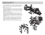
6.
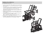
SECURELY assemble the SEAT PAD (22) to the BASE (1) using two RH CAPS (3),
two 3/8 X 32mm BOLTS (23), two 3/8" SAE WASHERS (6) and two 3/8" RH WASH-
ERS (7) as shown.
7.
From the side, SECURELY assemble the BACK PAD SUPPORT (24) to the BASE
(1) using two RH CAPS (3), one 3/8 X 95mm BOLTS (25), two 3/8" SAE WASHERS
(6), two 3/8" RH WASHERS (7) and one 3/8" LOW HT LOCK NUT (8).
At the rear of the BACK PAD SUPPORT, install using two RH CAPS (3), one 3/8 X
65mm BOLTS (37), two 3/8" SAE WASHERS (6), two 3/8" RH WASHERS (7) and
one 3/8" LOW HT LOCK NUT (8).
8.
SECURELY assemble the BACK PAD (22) to the BACK PAD SUPPORT using two
RH CAPS (3), two 3/8 X 76mm BOLTS (26), two 3/8" SAE WASHERS (6) and two
3/8" RH WASHERS (7).
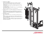
9.
Insert two KNEE PAD SUPPORTS (27) through the FLANGE BEARINGS (A) on the
LEFT and RIGHT PIVOT ARMS on the BASE (1) as shown.
Slide two 1” ID SINGLE SPLIT SHAFT COLLARS (28) over the SHAFTS of the
KNEE PAD SUPPORTS and SECURELY tighten set screws.
10.
SECURELY assemble two KNEE PADS (29) to the LEFT and RIGHT PIVOT ARMS
on the BASE (1) using four BLACK RH CAPS (38), four 3/8 X 36mm BOLTS (40),
four 3/8" SAE WASHERS (6) and four 3/8" RH WASHERS (7) as shown.
22
7
26
3
6
24
7
6
25
3
8
22
1
7
6
3
23
3
37
6
7
7
6
8
3
29
27
7
6
3
28
A
40


