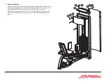
Hip Abduction / Adduction
1. Assembly Instructions
1.
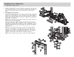
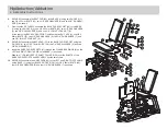
SECURELY assemble BASE (1) to the TOWER (2) using eight RH CAPS (3), three
3/8 X 92mm BOLTS (4), one 3/8 X 98mm BOLT (5), eight 3/8" SAE WASHERS (6),
eight 3/8" RH WASHERS (7) and four 3/8" LOW HEIGHT LOCK NUTS (8) as
shown.
2.
PRELIMINARY CABLE ROUTING
Wrap the CABLE (9) around one 4-1/2" PULLEY (10) and SECURELY assemble the
PULLEY to the PULLEY BRACKET on the TOWER (2) as shown using one BLACK
RH CAP (38), one RH CAP (3), one 3/8 X 44mm BOLT (13), two 3/8" SAE WASH-
ERS (6), two 3/8" RH WASHERS (7), one 2-7/8 X 1" CABLE CLIP (12) and one 3/8"
LOW HEIGHT LOCK NUT (8).
NOTE:
Make sure the CABLE is in the groove of the PULLEY and the CABLE CLIP
is positioned correctly, before tightening.
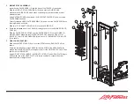
Route the threaded end of CABLE (9) through the TOWER (2) and around one 4-
1/2" PULLEY (10) and SECURELY assemble the PULLEY between the PLATES on
the TOWER as shown using four RH CAPS (3), two 3/8 X 49mm BOLTS (41), four
3/8" SAE WASHERS (6), four 3/8" RH WASHERS (7) and two 3/8" LOW HEIGHT
LOCK NUTS (8).
NOTE:
Make sure the CABLE is in the groove of the PULLEY before tightening.
Continue to route the threaded end of CABLE (9) through the TOWER (2) and
around two 4-1/2" PULLEYS (10) and SECURELY assemble the PULLEYS to the
TOWER as shown using two 3/8 X 63mm BOLTS (39), four 3/8 X 1/2" FLANGE
SPACERS (14) and two 3/8" LOW HEIGHT LOCK NUTS (8) as shown.
NOTE:
Make sure the CABLE is in the groove of the PULLEY before tightening.
7
1
2
6
4
3
6
3
7
8
10
7
13
38
6
12
7
7
41
3
6
8
3
6
9
2
1
14
39
14
8
9
10
2


