3.
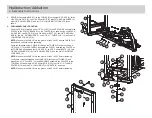
WEIGHT STACK ASSEMBLY:
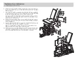
Insert the two GUIDE RODS (15) into the base of the TOWER (2) as shown.
Slide two WEIGHT STACK CUSHIONS (16) down over the GUIDE RODS .
Lubricate the GUIDE RODS with a slicon or teflon spray that is available at most
hardware stores.
Using EXTREME CARE, slide twenty 10 LB. WEIGHT PLATES (17) down over the
GUIDE RODS as shown.
Carefully slide the HEAD PLATE ASSEMBLY (18) down over the GUIDE RODS onto
the weight stack as shown.
Slide two 13/16" SHAFT COLLARS (19) over each GUIDE ROD.
4.
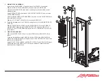
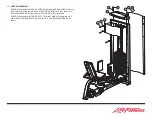
Route the threaded end of the CABLE (9) through the hole in the GUIDE ROD SUP-
PORT (20).
Slide the GUIDE ROD SUPPORT over the GUIDE RODS (15) on the TOWER (2)
and SECURELY assemble the GUIDE ROD SUPPORT using two 3/8 X 67mm
BOLTS (11), four 3/8" SAE WASHERS (6) and two 3/8" LOW HEIGHT LOCK NUTS
(8) as shown.
5.
FINAL CABLE ROUTING:
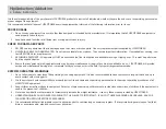
Slide one WEIGHT STACK PIN (21) over the STEM on the HEAD PLATE (18) as
shown.
Screw the threaded end of the CABLE (9) into the STEM of the HEAD PLATE far
enough that the HEAD PLATE just begins to lift off of the first WEIGHT PLATE. Then
tighten jam nut SECURELY.
Apply WEIGHT STACK LABELS to WEIGHT PLATES (17) and HEAD PLATE. Begin
with number one at the HEAD PLATE with larger numbers in consecutive order
towards bottom of weight stack.
20
6
11
21
18
17
15
19
16
8
6
9
2


