


8 | EN
Copyright © Liberty Pumps, Inc. 2021 All rights reserved.
5647000M
Discharge
Make all discharge connections. A check valve is required to
prevent the backflow of liquid after each pumping cycle. A gate
valve should follow the check valve to allow periodic cleaning of
the check valve or removal of the pump. The remainder of the
discharge line should be as short as possible with a minimum
number of turns to minimize friction head loss. Do not reduce the
discharge to below the pump outlet size. Larger pipe sizes may be
required to eliminate friction head loss over long runs. Contact
Liberty Pumps or other qualified person if questions arise
regarding proper pipe size and flow rates.
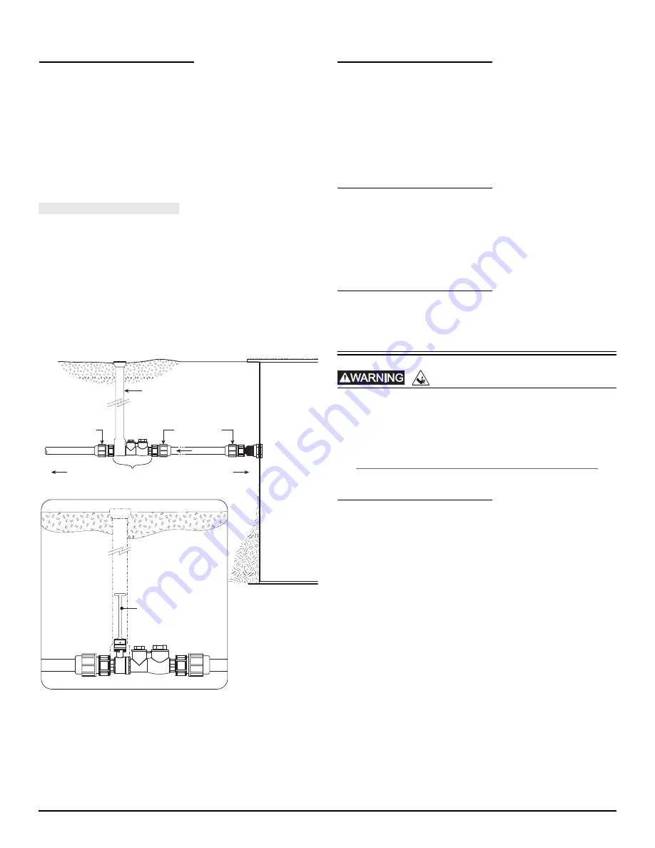
Pressure Sewer Applications
A redundant check valve assembly consisting of a curb stop and
check valve must be installed between the pump discharge and
the street main, as close to the public right-of-way as possible, on
all pressure (force main) sewer installations to protect from system
pressures. The curb stop valve is necessary to isolate the site from
the pressure sewer while the check valve provides redundant
protection against potentially detrimental backflow. All valves and
fittings should be rated for at least 200 PSI service. See Liberty
Pumps line of CSV-Series Curb Stop/Swing Check Valve
Assemblies and CK-Series Connection Kit.
Bulkhead
Connection
Pump Station
Compression
Adapter
Fitting
Curb Box
Compression
Adapter
Fitting
Valve Extension
Rod Shown
Curb Stop Valve/Swing
Check Valve Assembly
To Pump
To Main
Flow
Grade
Guide Rail System
If guide rails are used, refer to the separate instructions supplied
with the unit for proper installation and operation, making sure all
gaskets and components are present. Liberty Pumps GR20 Guide
Rail System features a self-aligning mounting bracket. Contact
Liberty Pumps for more information.
If guide rails are not used, complete all pump-mounted plumbing
at this time, being sure all gaskets and components are present.
Pump
Record information from pump nameplate onto the cover of these
instructions. Complete a visual inspection before lowering into
basin.
Place pump in basin being sure the mounting interface (i.e., guide
rail, torque stop) is engaged correctly.
Vent
Vent basin in accordance with applicable plumbing codes.
Operation
Energizing the control panel or breaker for the first time is
potentially dangerous. Licensed electrical personnel should
be present when the panel or breaker is energized for the first
time. If faults caused by damage or poor installation practices
have not been detected, serious damage, injury or death can
result when power is applied.
Starting System
1.
Verify all plumbing components in the basin are installed
correctly and functional. Verify all valves are open and ready
for pump use.
2.
Double check all wire connections. Re-tighten all factory and
field connections.
3.
Ensure pump has no obstructions.
4.
With all electrical and mechanical connections complete and
secure, turn on power to pump and control panel, if
applicable.
5.
Verify operation of the pump, floats, and alarm circuits.
6.
Run several cycles of water through the system to verify
correct control operation for the installation.
Be certain to complete adequate testing, especially on systems
with multiple pumps or custom control configurations.
RISK OF SERIOUS INJURY OR DEATH


