


6 | EN
Copyright © Liberty Pumps, Inc. 2021 All rights reserved.
5647000M
Wiring Instructions
Always disconnect pump(s) from power source(s) before
handling or making any adjustments to either the pump(s),
the pump system, or the control panel.
All installation and maintenance of pumps, controls,
protection devices, and general wiring shall be done by
qualified personnel.
All electrical and safety practices shall be in accordance with
the National Electrical Code
®
, the Occupational Safety and
Health Administration, or applicable local codes and
ordinances.
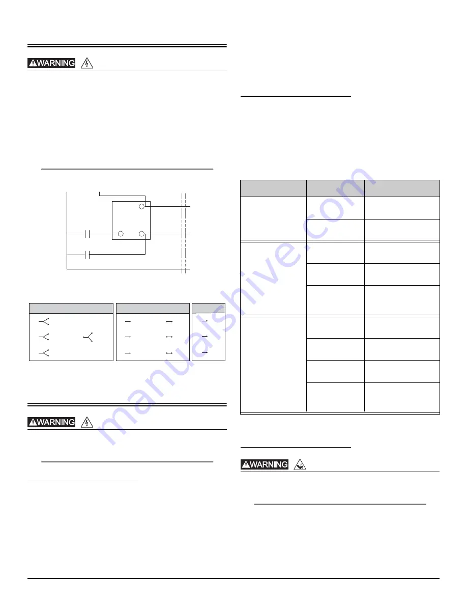
Figure 1. Wiring Diagram 1-Phase, External Capacitor
Figure 2. Wiring Connections 3-Phase
Preparation
Always disconnect pump(s) from power source(s) before
handling or making any adjustments to either the pump(s),
the pump system, or the control panel.
Prepare Basin
The basin required for effluent and sewage applications must be
sealed and vented to meet health and plumbing code
requirements. If replacing a previously installed pump, prepare the
basin by removing the old pump and cleaning any debris from the
basin. Inspect all remaining equipment in the basin including
guide rails, piping, valves, and electrical junction boxes (if present)
and repair or replace as appropriate. Ensure that control hardware
such as floats or pressure transducers are clean, properly adjusted,
and in good working order.
Pump installation should be at a sufficient depth to ensure that all
plumbing is below the frost line. If this is not feasible, remove the
check valve and size the basin and/or adjust pump differential to
accommodate the additional backflow volume. Consult Liberty
Pumps for details on how this should be done.
Pump Control and Alarm Floats
The engineering drawings will generally specify the levels for
Pump ON, Pump OFF, and HIGH LEVEL ALARM. If they are not
specified, the guidelines in Table 2 should be used to determine
float switch locations. The upper water level should be positioned
to minimize pump starts. The HIGH LEVEL ALARM float must be
above the Pump ON float but below any inlets. No float should be
set above the inlet to the basin.
System
Float
Levels
Factory set at float
tether 4”.
Factory set at float
tether 4”.
Level to top of motor
housing.
Minimum 1-1/2’ above
pump OFF level.
Minimum 1’ above
pump ON level and
below inlet pipe.
Level to top of motor
housing.
Minimum 1-1/2’ above
pump OFF level.
Minimum 1’ above
lead pump ON level.
Minimum 1’ above lag
pump ON level and
below inlet pipe.
Cutter and Impeller Free Movement Check
Wear Personal Protective Equipment to protect hands as
cutter blades have extremely sharp edges and present a
serious cutting hazard.
Do not connect any power to pump until this check is complete.
Manually rotate the cutter to check that it spins freely with very
little resistance. The cutter is located on the bottom of the pump.
The cutter can be carefully rotated by hand, or rotated by
inserting a tool into the cutter bolt. If rotating by hand, wear
protective gloves as the cutter and cutter plate have sharp edges.
RISK OF ELECTRIC SHOCK
RISK OF ELECTRIC SHOCK
Black (2)
Red (8)
White (7)
START CAP
RUN CAP
START
RELAY
L1
L2
5
1
2
EXTERNAL CONNECTIONS
L3
L2
L1
black
pink
violet
red
white
blue
brown
orange
yellow
440–480V 3PH
L3
L2
L1
black
pink
violet
575V 3PH
black
pink
violet
red
white
blue
brown
orange
yellow
L3
L2
L1
208V/230V 3PH
Table 2. Float Switch Installation Guidelines
Piggyback Switch
(1-Float System)
OFF
ON
Simplex Pump
Station
(3-Float System)
OFF
ON
HIGH LEVEL
ALARM
Duplex Pump
Station
(4-Float System)
OFF
Lead Pump ON
Lag Pump ON
HIGH LEVEL
ALARM
RISK OF SERIOUS INJURY OR DEATH


