contact shoes and one set of leading wheels
.
2 traction tyres which increase tractive power.
Reproduction
sloping rod drive with countershaft
and driving bar. Drive wheel dia.
=
46 mm.
Lighting
:
Three lanterns and driver's cab lighting
at both ends. 5 volt bulbs fed from a constant
voltage supply
.
The lighting changes according to
the direction of travel.
Simi
l
ar to the original, the rear right-hand lantern
is illuminated at night (as for 2040 with rear
lighting disc). Two lighting sockets for train
illumination 18 volts
.
Selection switch fitted in the
driver's cab 1 for rail or overhead traction with a
middle position for parking
.
A set of renumbering
decals with the locomotive
numbers 201-207 and neutral designations
is
included with every locomotive
.
This allows an
individuallocomotive
designation.
Selector
switch for "Type of Traction"
and
Lighting,
as for Locomotive 2040.
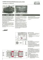
ede1 Overaillength
380 mm, weight 31 00 g.
Headlight
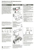
Fig.4
In order to rep
l
ace the bulb, the gi
l
t
headlight ring and white lantern unsert should be
pulled off.
Driver's
cab lighting
The driver's cab. plug-in bulb can be removed with
the aid of a pair of flat-nosed pliers. If this seems
to be too difficult, the upper part can be removed
after unscrewing the four, lower side fixing
screws
.
Gear box (Lower side)
Fig.5
The sliding contact shoe 2218 with plastic
holder (3) can be removed after pushing back the
brass contacl. Non-slip tyres
2018/4
and carbon
brushes 2110: Remove driving wheels (1) after
unscrewing the connecting rods. (Attention!
Carbon brushes (2) are sprung loaded).
The friction tyre
2018/4
and Current collector
carbon brush 2110 can be easily replaced.
Spare parts:
2018/4
Traction tyre for drive wheel dia
.
46 mm.
2045/1
Set of locomotive drive wheels dia
.
46mm
.
2120
Carbon brushes for locomotive gear
case and spring
.
2204
DC electric motor with long shaft
2218
Contact shoes with springs
5051/1
Plug-in micro-bulb 5 V, 33 mA.
- Page 9 -
Rack Electric
Locomotive
2046
Furka
-
Oberalp-Railway
FO HGe 2/2
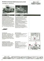
2046 Original
Fig
.
1
Onthe 12th
.
July
1917, the3.75
km
l
ong,
meter gauge Schöllenbahn
was inaugurated.
This electric
r
ack railway interconnected
the
Gotthard railway station of Göschenen and the
town of Andermatt. The first equipment consisted
of four twinaxle Electric Locomotives
Type HGe
2/2 No. 1-4 wh ich were built by messrs
.
SLM/BBC
.
Operated under normal friction drive
,
they are allowed to drive at 30 kmlh
,
as rack drive,
20 km/h
o
From the start
,
they were operated with
1200 volts D. C
.
In 1941 they were converted to
11 kV
16
1
1
2
Hz in order to prevent a multi-system
operation in the station at Andermatt, on the
Furka-Obera
l
p
railway, wh ich al ready used this
voltage
.
With this merger with the FO
,
the four
sm all E
l
ectric Locomotives
Type HGe 2/2 were
renumbered 21-24.
4
2046 Model
Fig
.
2
Tripie signallanterns
and driver
'
s cab
lighting at both ends
,
5 volt lighting system with
brightness regulation
.
Lights change depending
upon the direction of travel. As on their original
"Big Brothers", the rear
,
right-hand lantern is lit at
night. Two lighting sockets for train lighting
1
8 V.
Changeover
switch is fitted into the driver
'
s cab
for overhead or rail traction and a central Off
position
.
Built-in automatic overload switch for
heavy loading.
Length incl. buffers 280
.
mm
.
- Dismantling
- Spare Parts -
Driver's-cab
Internal
Lighting
The plug-in bulb in the driver
'
s
-
cab can be
replaced with the aid of a small pair of flat pliers. If
this is too difficult, then the roof should be
removed by unscrewing the 4 fixing screws (Fig
.
5)
.
Signal headlight
Fig.3
To replace the bulb, remove the headlight
ring and white reflector
.
The bulb can then be
pulled out with a pair of tweezers
.
Sliding
contact
shoe
Fig
.
4
After unscrewing the 7 screws
,
the lower
gearbox cover can be removed. The contact
shoes are pressed in
.
Dismantling
the locomotive
Fig. 5
Remove upper part
,
the dr
i
ver
'
s cab
lighting is now easily accessible.
Fig
.
6
Motor replacement:
Unscrew lead
weight
,
remove upper gearbox cover (2 screws)
.
Don't cross the grey, brown and white wires
.
Current
collectin9
carbon
brushes
for both
wheels.
To replace these
,
the gearbox must be removed
from the chassis
.
Unscrew connecting rods and
take out the sets of wheels. Attention! Current
collecting brushes are sprung loaded.
2120 Carbon
Brushes
for locomotive
with gear case and spring
.
Spare parts:
2205 Motor with single lead wormgear and
built-in overload switch
,
dia. 40 mm
.
Shaft dia
.
4mm.
2046/2
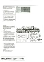
8 off Coupling hooks for a rack
locomotive with 4 coach es. Especially
recommended
for coaches with double coupling
hooks
,
as used on mountain railways
.
On pack is
required to convert a locomotive and 4 coaches
.
The uncoupling hook does not touch the rack rail
and therefore dosn't rattle
.
Coloured grey
.
5051/1
Plug-in micro-bulb 5 V
,
33 mA
.
Rack-Rail
Sections
for Mountainous
Sections
In addition to the normal friction drive through the
wheels, the locomotive power is also transfered
via cogs and rack rails
.
These can also be fitted on curved sections
.
Fig. 7, 8
When fitting the rack sections into the
rack sections clips
,
only a light pressure is
necessary to operated the clipping mechanisms.
At the same time, two retaining studs protrude
through the sleeper bed so that the system is
fixed in the track bed. The track section length is
independent of the track section length
.
The rack
sections can also be fitted into current track
sections. (Recommendation
:
appr
.
every
100 mm 1 clip).
Mountain
Operation
Throughout the world where grades are too steep
for normallocomotives,
rack railways, or "Cog
Trains", are used
.
And just like the real thing, you
can operate with LGB under these conditions
,
negotiating inclines of up to 25%
.
In other words,
over a stretch of 40 inches of track you can
increase (ordecrease)
the elevation by 10 inches
.
In alpine mounta
i
ns where shuttle service runs
from the valley up the mountain and back
,
fo
r
safety reasons the engines PUSH the cars up the
hili rather than PULL ~ a practice that should be
modelled in your LGB operation
.
In stretch es over hilly country
,
the cog engine can
of course be used to pull the train but the cars
should be outfitted with couplers at each end so
that they are double-coupled
.
Fig
.
9
At the beginning and end of mountain
grade, several short pieces (1015 or 1102)
should be used to allow for a more gentle leveling
.
Overhead wires on mountain stretches
:
The
tiltable masts (6300) are placed closer together.
- Page 10-
Open Air Operation
with a Catenary
System
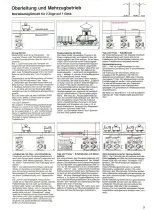
Connecting
possibilities
for indoo
r
and
outdoor
operation
Open air overhead
lines
are connected in a similar manner as those of an
indoor layout. Due to the fact however, that model
railway transformers
should only be installed
indoors, it is necessary to supply the low
-
voltage
to a controller wh ich may be fitted outdoors in a
sheltered spot.
Two such controllers are available from the LGB
assortment:
5007 or 5012
:
Electronic Controllers for up to
2 amps
.
These controllers should be connected
to the Large Transformer
5006
.
Three different
connecting possibilities can be selected
.
.
Naturallythis
transformer is also ideally suited for
large indoor layouts
.
Fig
.
1
Catenary system on a garden layout.
Connecting-possibilities
for the Controller to the
Transformer
5006
:
5007 to dc voltage (22 volts, 2 amps
.
),
connections
1-2
or to ac voltage (17 volts, 1
.
2 amps.),
connections 3-4
5012 only to dc voltage (22 volts
,
2 amps.),
connections
1-2
The necessary interconnecting
(hook-up) leads
are supplied with each controller.
Fig
;
2
2 x 5006
+
2
x
5012
Driving power capacity
:
2 x 18/22 volts 2 amps
.
dc
.
Switching and lighting: 2 x 17 volts, 1
.
2 amps. AC
.
Both Controller 5012 should be connected to the
DC terminals 1-2 of the Transformer
5006.
Weather-proof
overhead
lines
All metal parts of the LGB-overhead
l
ines,
transverse and overhead wires are manufac-
tured in non-rusting steel and therefore are
suitable for outdoor operation in all weathers
.
For the best results however
,
it is recommen-
ded, that the supply voltage should be fed
,
through a number of connecting masts 6001.
Fig.
3:
1 x 5006
+
1 x 5012
+
1 x 5007
D
r
iving power
:
18/22 volts, 2 amps
+
18 volts
,
1.2 amps DC
Switching and lighting: to separate Transformer
5006 ac.
The Controller 5012 should only be connected to
the dc connections
1-2 whereas the Controller
5007 is supplied with ac voltage from connect
i
ons
3-4.
Care of Catenary
System
To improve the electrical contact resistance
and also to reduce wear of the pantograph
contacts
,
the overhead wires should be
occasionally
oiled with Cleaning Oil 5001
wh ich has been applied to a clean cloth.
Practical tip: Wind a sm all amount of
cotton-wool around the pantograph contact,
soak with cleaning oil
,
now switch the
locomotive to rail traction and drive around the
overhead section a few times.

