


22
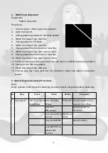
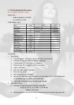
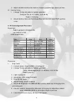
4. DMD Panel Alignment
Equipment:
-
Pattern Generator
Procedure:
1. Connect power, Video signal into projector.
2. Light on projector
3. Change pattern generator to full white pattern.
4. Watch the image if any pixel lost
5. Change pattern to full black.
6. Watch the image if any pixel lost
7. Change pattern from full black to full white.
8. Watch the image if any pixel can not return
9. Change pattern from full black to full white.
10. Watch the image if any pixel can not return
11. If above 8 step has some pixel lost or can not return, it
s DMD chip has pixel defect
12. Change to the Slid Line pattern
13. Watch the image if any pixel lost
14. If above step has some pixel lost, it
s conductive rubber has defect or assembly
loosed.
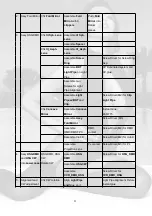
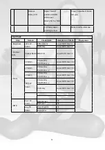
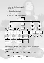
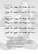
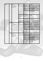
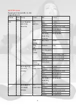
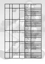
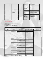
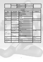
5. Optical Engine Assembly Procedure
Note:
Every operator must check the dust/chip on every optical component before assembly.
No
.
Stop
Check
Action
Review
Equipment
Chk Timing Tape of
Color Wheel
Assemble
Color
Wheel
Rotate CW Screw Driver(M3) and Jig
fixture for Color Wheel
Assemble
CW_Sensor
Screw Driver(M2) for
CW/Sensor
Assemble UV-IR on
PLT CW
Direction of
UV-IR
Assemble
PLT CW
Screw Driver(M3)
1 Assy Hsg CW
Tape
CW FPC
and
Sensor FPC
together
Summary of Contents for RD-JT51
Page 13: ...13 2 JT50 52 ...
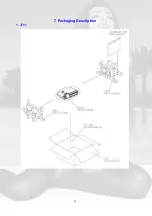
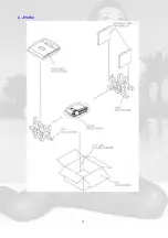
Page 14: ...14 7 Packaging Description 1 JT51 ...
Page 15: ...15 2 JT50 52 ...
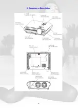
Page 16: ...16 8 Appearance Description ...
Page 53: ...ëí 5 PFC BOARD 6 DC DC BOARD ...
Page 54: ...ëì JT50 52 1 Final Assembly Trouble Shooting Guide ...
Page 55: ...ëë ...
Page 56: ...ëê 2 Engine Assembly Trouble Shooting Guide ...
Page 58: ...ëè 4 Power Supply Trouble Shooting Guide PFC BOARD DX850 DC DC BOARD ...
Page 59: ...5ç 5 DMD Block Trouble Shooting Guide ...
Page 60: ...êð ...
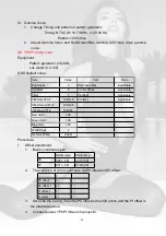
Page 74: ...éì Step 7 Download finished Step 8 Turn off the power switch ...
Page 81: ......


