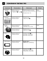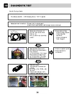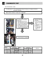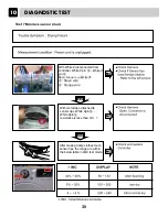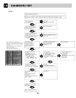
COMPONENT TESTING TIPS
7
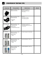
13.Steam generator
Measure resistance of the
Terminal to terminal
Measure resistance of the
Following terminal
Measure resistance of the
Following terminal
White housing
-.2 wire (Two of five colors)
Measure resistance of the
Following terminal
Blue housing
-.2wire
Measure resistance of the
Following terminal
Measure resistance of the
Following terminal
14. Inlet. valve
15.Convert.valve
16.LID switch
17.Thermistor
(Comp out)
18.Thermistor
(Eva In)
Left picture
-.plate
White housing
-.2wire
Blue housing
-.2wire
17
Summary of Contents for RC7055*P*Z
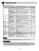
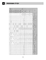
Page 9: ...PROGRAM CYCLE 4 9 ...
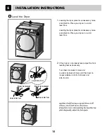
Page 12: ...INSTALLATION INSTRUCTIONS 5 12 ...
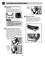
Page 14: ...MAINTENANCE INSTRUCTIONS 6 1 2 4 5 6 7 CAUTION 3 8 14 ...
Page 15: ...COMPONENT TESTING TIPS 7 15 ...
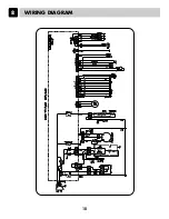
Page 18: ...WIRING DIAGRAM 8 18 ...
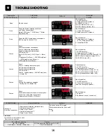
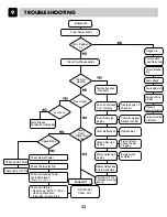
Page 20: ...TROUBLESHOOTING 9 20 ...
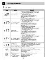
Page 21: ...Error Mode TROUBLESHOOTING 9 21 ...
Page 55: ...AUGUST 2011 PRINTED IN KOREA P No 3828EL9001Y ...


