


62 | LIMITS / PLACEMENT
LIMITS / PLACEMENT | 63
Piping Limitations and Placement Considerations
MUL
TI V W
ater IV Source Unit Engineering Manual
© LG Electronics Canada, Inc., North York, ON Canada. All rights reserved. “LG” is a registered trademark of LG Corp.
.
© LG Electronics Canada, Inc., North York, ON Canada. All rights reserved. “LG” is a registered trademark of LG Corp.
Table 34: Heat Pump Triple-Frame Connection Pipe Sizes.
Conditional Applications
Conditional applications are computed in LATS. See below for an explanation of when pipes are upsized.
If the equivalent length between the first Y-branch to the farthest indoor unit is >131 feet (up to 295 feet maximum):
• Pipe segment diameters between the first Y-branch and the second Y-branch must be sized up by one. This applies to both liquid and vapor
pipes. If the next size up is not available, or if the piping segment diameters are the same as main pipe (A) diameters, sizing up is not
possible.
• While calculating the entire refrigerant pipe length, pipe lengths for ΣB must be multiplied by two: A+(ΣBx2)+ΣC ≤1,640 feet.
• Length of pipe (C) from each indoor unit to the closest Y-branch or header ≤ 131 ft.
• [Length of pipe from water source unit to farthest indoor unit (A+B+C)] - [Length of pipe from water source unit to closest indoor unit
(A+B+C)] ≤131 feet.
If the pipe (B) diameters after the first branch are bigger than the main pipe (A) diameters, pipe (B) must be changed to match main pipe (A)
sizes.
Example: When an indoor unit combination ratio of 120% is connected to a 24-ton water source unit:
Water source unit main pipe (A) diameters: 1-3/8 inches (vapor) and 5/8 inches (liquid).
1. Pipe (B) diameters: 1-3/8 (vapor) and 3/4 (liquid) (after the first branch, when indoor unit combination ratio is 120% [26 tons]).
2. After the first branch, pipe (B) diameters must be changed to 1-3/8 inches (vapor) and 5/8 inches (liquid) to match main pipe (A) sizes.
Instead of using the total indoor unit capacity to choose main pipe (A) diameters, use water source unit capacity to choose downstream main pipe
(A) diameters.
Do not permit connection pipes (B) from branch to branch to exceed main pipe (A) diameters as indicated by water source unit.
capacity. Example: When an indoor unit combination ratio of 120% is connected to a 20-ton water source unit (24 tons), and indoor unit with
a 7,000 Btu/h capacity is located at the first branch:
1. Main pipe (A) diameters on a 20-ton water source unit: 1-1/8 inches (vapor) and 5/8 inches (liquid).
2. Pipe diameters between first and second branches, however, are: 1-3/8 (vapor) and 3/4 (liquid) (connected downstream indoor unit
capacity is 20 tons).
3. If main pipe (A) diameters of a 20-ton water source unit are 1-1/8 (vapor) and 5/8 (liquid), then the pipe diameters between the first
and second branches must be changed to match.
PIPING LIMITATIONS
For Systems Designed for Heat Pump Configuration
Following pages present Multi V Water V piping limitations and are for illustrative purposes only. Designers MUST use LATS when designing LG VRF
systems.
Heat Pump Outdoor Unit Service Port Detail
PIPING LIMITATIONS
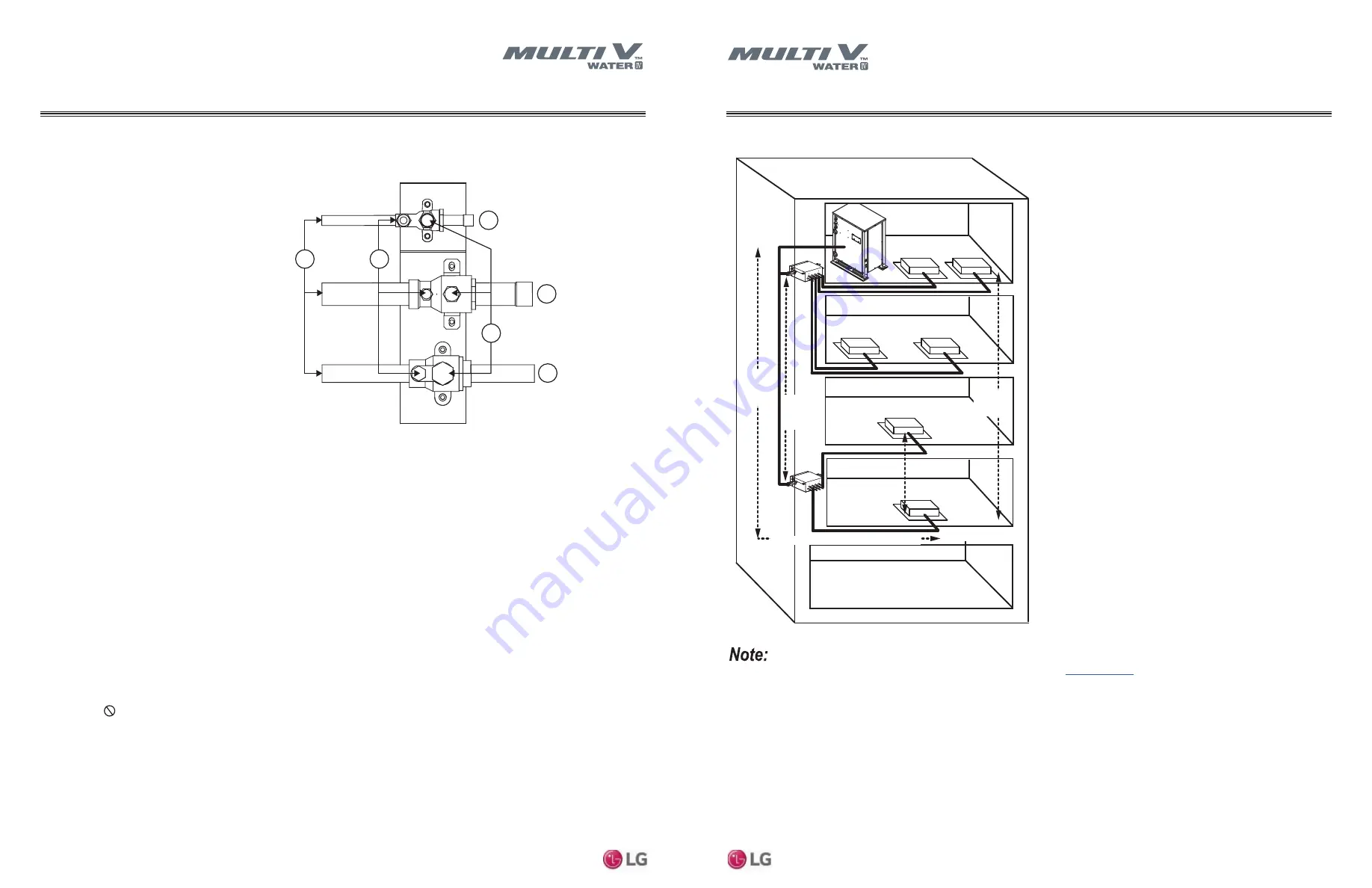
For Systems Designed for Heat Recovery Configuration
Following pages present Multi V Water V piping limitations and are for illustrative purposes only. Designers MUST use LATS when designing LG VRF
systems.
Figure 27: Typical Heat Recovery System Building Layout with Piping Limitations.
E lev ation
Differential
WS U to
IDU: 164'
M ax imum Total Piping L ength: 1, 640'
E lev ation
Differential
IDU to IDU on
same H RU: 49'
E lev ation
Differential
IDU to IDU: 131'
E lev ation
Differential
H RU to
H RU: 98'
L ongest pipe length: 656' actual ( 738' eq uiv )
For Heat Recovery Unit information, refer to the applicable Engineering Manual on
www.lghvac.com
.
4
Tools
Verify the tools listed below are available for use at the installation site:
Piping
Multi V Water 5 Piping and Service Ports
LG Multi V Water 5 systems can be configured to operate as either
a heat pump or a heat recovery system. The piping MUST be
installed to the correct outdoor unit service ports according to
project specifications or the system will not operate properly. See
below for the piping installation differences between heat pump and
heat recovery systems.
Heat Pump Outdoor Unit Service Port Detail
1. Liquid piping service port (back
seated type with right hand thread).
2. Service port NOT used for heat
pump systems. Keep closed and
capped.
3. Vapor piping service port (back
seated type with right hand thread).
4. Stem head access with factory-
provided cap.
5. Schrader ports with factory-
provided cap.
6. Service port piping to connect to
field piping.
Heat Recovery Outdoor Unit Service Port Detail
1. Liquid piping service port (back
seated type with right hand thread).
2. Low pressure vapor piping service
port (back seated type with right
hand thread).
3. Vapor piping service port (back
seated type with right hand thread).
4. Stem head access with factory-
provided cap.
5. Schrader ports with factory-provided
cap.
6. Service port piping to connect to
field piping.
Piping Selection
ACR-rated, seamless phosphorous deoxidized copper (UNS
C12200 DHP class) is the only approved refrigerant pipe material
for LG Multi V products. Approved piping will be marked “R-410A
rated” along the length of the tube.
• Drawn temper (rigid) ACR copper tubing is available in sizes 3/8
through 2-1/8 inches (ASTM B 280, clean, dry and capped).
• Annealed temper (soft) ACR copper tubing is available in sizes
1/4 through 2-1/8 inches (ASTM B 280, clean, dry, and capped).
Handling the Piping
To avoid operation failure, a VRF system CANNOT have
contaminants or moisture in the piping network. Piping must be
kept clean, dry, and air tight. Commercially available piping,
however, often contains dust and other materials. Clean it with a
dry inert gas, and keep it capped until ready for installation. While
installing, prevent dust, water, or other contaminants from entering
the piping. When cutting the piping, hold it so copper shavings do
not fall into it, and properly remove all burrs with a de-burring tool.
Ream all piping to its full inside diameter; correctly reamed piping
will provide an excellent surface for a tight seal.
When bending piping, try to keep the number of bends to a
minimum, and use the largest radius possible to reduce the
equivalent length of installed pipe. If an obstacle is in the path of
the planned refrigerant pipe run, it is preferable to route the pipe
over the obstacle, with the length of the horizontal section of pipe
above or below the obstacle be a minimum of three (3) times the
longest vertical rise (or fall) at either end of the segment.
Piping Expansion
Expansion and contraction must be allowed in the design to avoid
fitting and piping fatigue failures. A vapor line in a Multi V water
system can change from 50° to 170° when switching from cooling
to heating. This can cause up to 1-3/8 inches expansion /
contraction per 100 feet of pipe, or about 0.001 inch / °F per 10 feet
of pipe. When a segment of pipe is mounted between 2 fixed
points, provisions must be provided to allow pipe expansion to
naturally occur, generally by expansion Loops or U-bends.
Flaring the Piping
When flaring the piping, use a dedicated R-410A flaring tool; use
only synthetic oil between the nut and the flare (not inside the
piping) to achieve correct torque and prevent leaks. Flares must be
deeper to handle the higher pressures of R-410A.
When brazing the piping, always use 15%
silver braze and a nitrogen purge. Similar to
piping medical gas, flow the nitrogen
through the piping at 1 to 3 psig to prevent
oxidation.
• Screw Drivers
(JIS for terminal screws, Flat, Phillips)
• Pliers
• Wire Strippers, Cutters, and Crimpers
• Hammer
• Adjustable Wrenches
• Drill and Bits
• Hole Saw
• Utility Knife
• Drop Cloth
• Pipe Cutter / Reamer
• Acetylene Brazing Outfit
• Brazing Material —15 % silver only
• Digital Multimeter and Amp Clamp
• R-410A Flaring Tool
• Torque Wrench Set
• Dedicated R-410A Refrigerant Manifold Gauge
• Dedicated 5/16" Premium Hoses
• Nitrogen regulator (for 550# test)
• 1/4" to 5/16" Hose Adapters (if needed)
• Nitrogen Tank
• Electronic Leak Detector
• 5/16" Schrader Core Removal Tool
• Vacuum Micron Gauge
• Good Quality Digital Charging Scale
• Vacuum Pump and Fresh Oil
• Refrigerant Recovery Unit and Tank
• Wall thickness must meet local code requirements and be
approved for a maximum operating pressure of 551 psi.
• LG recommends soft copper use to be limited to 1/2 inches.
Use hard drawn for larger sizes to avoid sags and kinks that
lead to oil trapping.
NOTE
!
Proper R-410A Flare.
Heat Recovery Outdoor Unit Service Port Diagram.
Heat Pump Outdoor Unit Service Port Diagram.
1
2
3
6
5
4
1
2
3
6
5
4
4
Tools
Verify the tools listed below are available for use at the installation site:
Piping
Multi V Water 5 Piping and Service Ports
LG Multi V Water 5 systems can be configured to operate as either
a heat pump or a heat recovery system. The piping MUST be
installed to the correct outdoor unit service ports according to
project specifications or the system will not operate properly. See
below for the piping installation differences between heat pump and
heat recovery systems.
Heat Pump Outdoor Unit Service Port Detail
1. Liquid piping service port (back
seated type with right hand thread).
2. Service port NOT used for heat
pump systems. Keep closed and
capped.
3. Vapor piping service port (back
seated type with right hand thread).
4. Stem head access with factory-
provided cap.
5. Schrader ports with factory-
provided cap.
6. Service port piping to connect to
field piping.
Heat Recovery Outdoor Unit Service Port Detail
1. Liquid piping service port (back
seated type with right hand thread).
2. Low pressure vapor piping service
port (back seated type with right
hand thread).
3. Vapor piping service port (back
seated type with right hand thread).
4. Stem head access with factory-
provided cap.
5. Schrader ports with factory-provided
cap.
6. Service port piping to connect to
field piping.
Piping Selection
ACR-rated, seamless phosphorous deoxidized copper (UNS
C12200 DHP class) is the only approved refrigerant pipe material
for LG Multi V products. Approved piping will be marked “R-410A
rated” along the length of the tube.
• Drawn temper (rigid) ACR copper tubing is available in sizes 3/8
through 2-1/8 inches (ASTM B 280, clean, dry and capped).
• Annealed temper (soft) ACR copper tubing is available in sizes
1/4 through 2-1/8 inches (ASTM B 280, clean, dry, and capped).
Handling the Piping
To avoid operation failure, a VRF system CANNOT have
contaminants or moisture in the piping network. Piping must be
kept clean, dry, and air tight. Commercially available piping,
however, often contains dust and other materials. Clean it with a
dry inert gas, and keep it capped until ready for installation. While
installing, prevent dust, water, or other contaminants from entering
the piping. When cutting the piping, hold it so copper shavings do
not fall into it, and properly remove all burrs with a de-burring tool.
Ream all piping to its full inside diameter; correctly reamed piping
will provide an excellent surface for a tight seal.
When bending piping, try to keep the number of bends to a
minimum, and use the largest radius possible to reduce the
equivalent length of installed pipe. If an obstacle is in the path of
the planned refrigerant pipe run, it is preferable to route the pipe
over the obstacle, with the length of the horizontal section of pipe
above or below the obstacle be a minimum of three (3) times the
longest vertical rise (or fall) at either end of the segment.
Piping Expansion
Expansion and contraction must be allowed in the design to avoid
fitting and piping fatigue failures. A vapor line in a Multi V water
system can change from 50° to 170° when switching from cooling
to heating. This can cause up to 1-3/8 inches expansion /
contraction per 100 feet of pipe, or about 0.001 inch / °F per 10 feet
of pipe. When a segment of pipe is mounted between 2 fixed
points, provisions must be provided to allow pipe expansion to
naturally occur, generally by expansion Loops or U-bends.
Flaring the Piping
When flaring the piping, use a dedicated R-410A flaring tool; use
only synthetic oil between the nut and the flare (not inside the
piping) to achieve correct torque and prevent leaks. Flares must be
deeper to handle the higher pressures of R-410A.
When brazing the piping, always use 15%
silver braze and a nitrogen purge. Similar to
piping medical gas, flow the nitrogen
through the piping at 1 to 3 psig to prevent
oxidation.
• Screw Drivers
(JIS for terminal screws, Flat, Phillips)
• Pliers
• Wire Strippers, Cutters, and Crimpers
• Hammer
• Adjustable Wrenches
• Drill and Bits
• Hole Saw
• Utility Knife
• Drop Cloth
• Pipe Cutter / Reamer
• Acetylene Brazing Outfit
• Brazing Material —15 % silver only
• Digital Multimeter and Amp Clamp
• R-410A Flaring Tool
• Torque Wrench Set
• Dedicated R-410A Refrigerant Manifold Gauge
• Dedicated 5/16" Premium Hoses
• Nitrogen regulator (for 550# test)
• 1/4" to 5/16" Hose Adapters (if needed)
• Nitrogen Tank
• Electronic Leak Detector
• 5/16" Schrader Core Removal Tool
• Vacuum Micron Gauge
• Good Quality Digital Charging Scale
• Vacuum Pump and Fresh Oil
• Refrigerant Recovery Unit and Tank
• Wall thickness must meet local code requirements and be
approved for a maximum operating pressure of 551 psi.
• LG recommends soft copper use to be limited to 1/2 inches.
Use hard drawn for larger sizes to avoid sags and kinks that
lead to oil trapping.
NOTE
!
Proper R-410A Flare.
Heat Recovery Outdoor Unit Service Port Diagram.
Heat Pump Outdoor Unit Service Port Diagram.
1
2
3
6
5
4
1
2
3
6
5
4