


ONE-WAY | 17
One-W
ay Ceiling Cassette Product Data
'XHWRRXUSROLF\RIFRQWLQXRXVSURGXFWLQQRYDWLRQVRPHVSHFL¿FDWLRQVPD\FKDQJHZLWKRXWQRWL¿FDWLRQ
©
/*(OHFWURQLFV86$,QF(QJOHZRRG&OLIIV1-$OOULJKWVUHVHUYHG³/*´LVDUHJLVWHUHGWUDGHPDUNRI/*&RUS
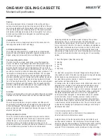
ONE-WAY CEILING CASSETTE
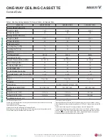
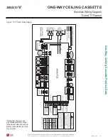
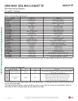
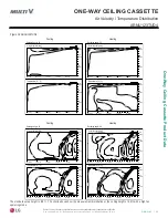
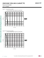
Refrigerant Flow Diagram
Figure 6: TU, TT Frame Piping Diagram.
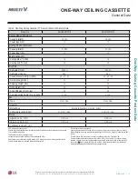
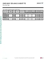
Model
Liquid (inch)
Gas (inch)
78)UDPHV
ARNU073TUD4
1/4
1/2
ARNU093TUD4
ARNU123TUD4
77)UDPHV
ARNU183TTD4
1/4
1/2
ARNU243TTD4
3/8
5/8
Thermistor
Description
TH1
Return air thermistor
TH2
Pipe in thermistor
TH3
Pipe out thermistor
Heat Exchanger
C.F.F.
lndoor unit
EEV
Filter
Filter
Th3
Th2
Th1
Heating
Cooling
Table 6: TU, TT Frame Refrigerant Pipe Connection Port Diameters.
TU and TT Frames
Table 7: TU, TT Frame Thermistors.


