


GUIDELINES | 131
Application Guidelines
'XHWRRXUSROLF\RIFRQWLQXRXVSURGXFWLQQRYDWLRQVRPHVSHFL¿FDWLRQVPD\FKDQJHZLWKRXWQRWL¿FDWLRQ
©
/*(OHFWURQLFV86$,QF(QJOHZRRG&OLIIV1-$OOULJKWVUHVHUYHG³/*´LVDUHJLVWHUHGWUDGHPDUNRI/*&RUS
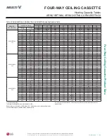
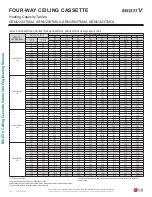
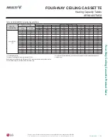
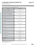
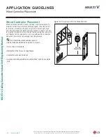
APPLICATION GUIDELINES
General Drain Piping Information
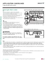
(QVXUHWKHLQGRRUXQLWUHIULJHUDQWSLSLQJGUDLQSLSLQJDQGSRZHUZLULQJ
FRPPXQLFDWLRQFDEOHVDUHSURSHUO\VXSSRUWHGZLWKDQFKRUEROWVDQGFODPS
KDQJHUVSRVLWLRQHGDWWRIRRWLQWHUYDOV
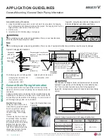
Figure 106: Properly Insulating the Drainage Piping.
Insulation
Requir ed
Insulation
Not Required
Properly Fitting Insulation
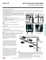
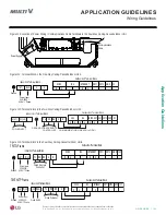
Figure 107: Example of a Common Indoor Unit Drainage System.
Drain Piping
• Drain piping must have down slope (1/50 to 1/100).
• Any holes through the ceilings, walls, etc., must be large enough to accom-
modate the drain piping and insulation.
• The outside diameter of the drain connection on the indoor unit is 1-1/4
inches.
• Drain piping material is polyvinyl chloride pipe (1 inch).
7RSUHYHQWUHYHUVDOÀRZGRQRWSURYLGHXSDQGGRZQVORSH
Drain Leak Test
A leak test must be performed 24 hours after the drainage system has been
installed.
Drain Pipe Insulation
To prevent condensate from forming on the drain piping, field-
supplied 5/16 inch thick polyethylene insulation must be properly installed.
Common Indoor Unit Drainage System
It is usual work practice to connect individual
indoor unit drain pipes to one common indoor unit
drainage system.
The diameter of the common vertical drain pipe
must be as large as necessary.
The diameter of
the horizontal pipe must be the same or larger
than the vertical drain pipe. To avoid property
damage in the event of the primary drain becom-
ing clogged, and to optimize drain system perfor-
mance, it may be prudent to install a secondary
drain line.
Design the drain system to plan for winter opera-
tion (condensate line may freeze up if condensate
does not properly drain away). Drain all gener-
ated condensate from the external condensate
pan to an appropriate area. Install a trap in the
condensate lines as near to the indoor unit coil as
possible. To prevent overflow, the outlet of each
trap must be positioned below its connection to
the condensate pan. All traps must be primed,
insulated, and leak tested.
Common horizontal drain pipe
1/50 to 1/100 Slope
27-1/2 in.
(Maximum pump
lift distance
[depends on indoor
unit type]).
Include trap
at the end.
45° to 60° Angle
Position the vent
down to prevent
debris from entering
the system
45° to 60° Angle
45° to 60° Angle
45° to 60° angle for protection against overflow
Common
vertical
drain pipe
Maintenance
drain port
Upward
routing
not allowed
Pipe clamp
Indoor unit
Figure 105: Drain Piping Slope.
•
,WLVUHFRPPHQGHGWKDWDGHGLFDWHGGUDLQSLSHEHLQVWDOOHGIRUWKHDLUFRQGLWLRQLQJV\V
-
WHP,IWKHLQGRRUXQLWGUDLQDJHV\VWHPLVVKDUHGZLWKDUDLQZDWHUGUDLQZDVWHZDWHU
RUDQ\RWKHUW\SHRIEXLOGLQJGUDLQV\VWHPEDFNIORZOHDNVLFHPD\IRUPRUQR[LRXV
RGRUVPD\LQILOWUDWHWKHDLUFRQGLWLRQLQJV\VWHP
•
,QVWDOODWUDSLIWKHGUDLQDFFHVVWRWKHRXWVLGHIDFHVDQXQGHVLUDEOHORFDWLRQLH
VHZHURWKHUZLVHQR[LRXVRGRUVPD\LQILOWUDWHWKHDLUFRQGLWLRQLQJV\VWHP
Flexible Drain Hose, continued.
When the receiving drain line is mounted horizontal, connect the inverted trap to the top half of the pipe. The connection point of the inverted
trap to the building drain pipe must always be to the top half of the pipe and must never be over 45° either side of the upper most point of the
horizontal building drain line.
If connecting to a vertical drain line or plumbing system vent line, connect the
,'8FRQGHQVDWHSXPSGLVFKDUJHOLQHXVLQJD<¿WWLQJZLWKWKHGRXEOHHQG
RIWKH<¿WWLQJIDFLQJXS:KHQFRQQHFWLQJWRDYHUWLFDOGUDLQOLQHLQFOXGH
an inverted trap at the top of the IDU condensate pump discharge riser before
FRQQHFWLRQWRWKH<¿WWLQJ


