


128 | GUIDELINES
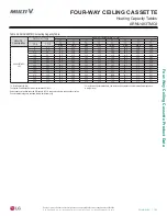
MUL
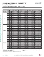
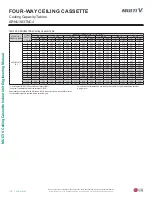
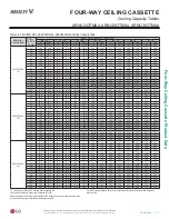
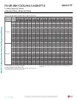
TI V Ceiling Cassette Indoor Unit Engineering Manual
'XHWRRXUSROLF\RIFRQWLQXRXVSURGXFWLQQRYDWLRQVRPHVSHFL¿FDWLRQVPD\FKDQJHZLWKRXWQRWL¿FDWLRQ
©
/*(OHFWURQLFV86$,QF(QJOHZRRG&OLIIV1-$OOULJKWVUHVHUYHG³/*´LVDUHJLVWHUHGWUDGHPDUNRI/*&RUS
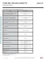
APPLICATION GUIDELINES
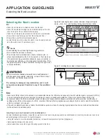
Selecting the Best Location
Selecting the Best Location
Do’s
• Place the unit where air circulation will not be blocked.
• Place the unit where drainage can be obtained easily and to mini-
mize the length of the condensate drain piping.
• Place the unit where noise prevention is taken into consideration.
• Ensure there is sufficient space from the ceiling and floor.
• Ensure there is sufficient maintenance space.
• Locate the indoor unit in a location where it can be easily connect-
ed to the outdoor unit / heat recovery unit.
Installing in an Area Exposed to Unconditioned Air
In some installation applications, areas (floors, walls) in some rooms may be exposed to unconditioned air (room may be above or next to an
unheated garage or storeroom). To countermeasure:
• Verify that carpet is or will be installed (carpet may increase the temperature by three [3] degrees).
• Add insulation between the floor joists.
• Install radiant heat or another type of heating system to the floor.
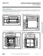
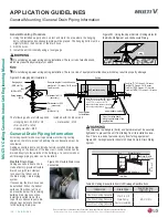
Figure 96: Selecting the Best Location / Minimum Clearance Require-
ments — One-, Two-, and Four-Way Ceiling-Cassette Indoor Units.
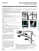
Install a ventilation fan
with sufficient capacity
Heat or steam source
Indoor Unit
Include enough
distance
Figure 97: Installing Near a Heat or Steam Source.
Don’ts
•
$YRLGLQVWDOOLQJWKHXQLWQHDUKLJKIUHTXHQF\JHQHUDWRUV
•
'RQRWLQVWDOOWKHXQLWQHDUDGRRUZD\
•
7KHXQLWPXVWQRWEHLQVWDOOHGQHDUDKHDWRUVWHDPVRXUFHRU
ZKHUHFRQVLGHUDEOHDPRXQWVRIRLOLURQSRZGHURUIORXUDUHXVHG
7KHVHPDWHULDOVPD\JHQHUDWHFRQGHQVDWHFDXVHDUHGXFWLRQLQ
KHDWH[FKDQJHUHIILFLHQF\RUWKHGUDLQSXPSWRPDOIXQFWLRQ,IWKLV
LVDSRWHQWLDOSUREOHPLQVWDOODYHQWLODWLRQIDQODUJHHQRXJKWRYHQW
RXWWKHVHPDWHULDOV
The unit may be damaged, may malfunction, and / or will
not operate as designed if installed in any of the conditions
listed.
7KHXQLWPXVWQRWEHLQVWDOOHGZKHUHVXOIXULFDFLGDQGÀDPPDEOHRU
FRUURVLYHJDVHVDUHJHQHUDWHGYHQWHGLQWRRUVWRUHG7KHUHLVULVNRI
¿UHH[SORVLRQDQGSK\VLFDOLQMXU\RUGHDWK
Ceiling
Ceiling Tile
Ceiling Tile
Floor
Unit: Inch
39-3/8
or more
13/32
or more
19-11/16
or more
19-11/16
or more
11-13/16
or less
19/32 ±1/8
1-3/16 ± 1/8
* Four-Way TQ/TR Frames
* Four-Way TP/TN/TM Frames
“A”
“A”
Four-Way <36,000 Btu/h: 70-7/8 to 141-23/32 inches
Four-Way >36,000 Btu/h: 70-7/8 to 165-11/32 inches
One-Way
Only: 7-7/8 or more
One-Way: 70-7/8 to 129-15/16 inches
Two-Way: 70-7/8 to 129-15/16 inches
* Two-Way TS Frames
13/16 ±1/8
•
,QGRRUXQLWV,'8VVKRXOGQRWEHSODFHGLQDQHQYLURQPHQWZKHUHWKH,'8VPD\EHH[SRVHGWRKDUPIXOYRODWLOHRUJDQLFFRPSRXQGV92&V
RULQHQYLURQPHQWVZKHUHWKHUHLVLPSURSHUDLUPDNHXSRUVXSSO\RULQDGHTXDWHYHQWLODWLRQ,IWKHUHDUHFRQFHUQVDERXW92&VLQWKH
HQYLURQPHQWZKHUHWKH,'8VDUHLQVWDOOHGSURSHUDLUPDNHXSRUVXSSO\DQGRUDGHTXDWHYHQWLODWLRQVKRXOGEHSURYLGHG$GGLWLRQDOO\LQ
EXLOGLQJVZKHUH,'8VZLOOEHH[SRVHGWR92&VFRQVLGHUDWKLUGSDUW\IDFWRU\DSSOLHGHSR[\FRDWLQJWRWKHIDQFRLOVIRUHDFK,'8ZKHUHWKH
HQWLUHFRLOLVGLSSHGQRWVSUD\HG
•
,IWKHXQLWLVLQVWDOOHGQHDUDERG\RIZDWHUWKHLQVWDOODWLRQSDUWVDUHDWULVNRIFRUURGLQJ$SSURSULDWHDQWLFRUURVLRQPHWKRGVPXVWEHWDNHQ
IRUWKHXQLWDQGDOOLQVWDOODWLRQSDUWV


