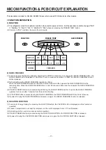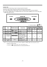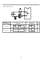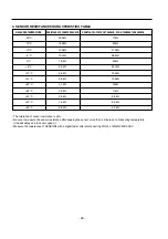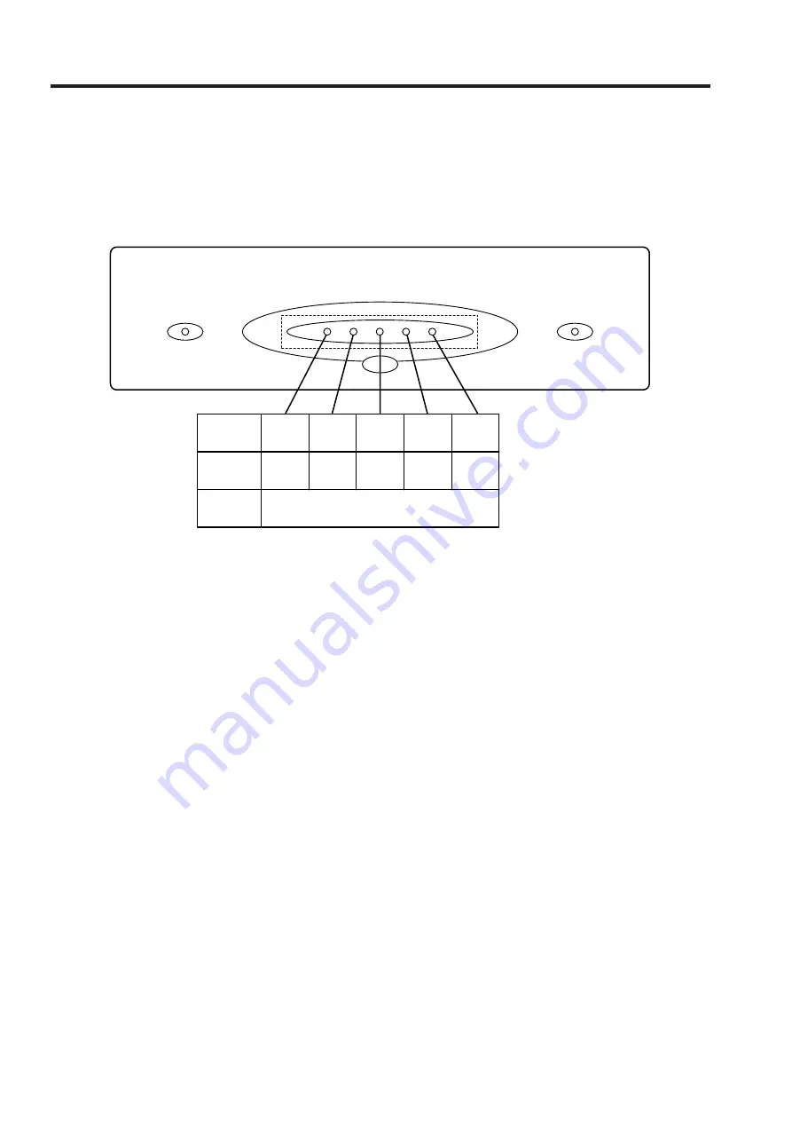
NOTCH
TEMP(ûC)
ROOM
Min
Min/
Mid
Mid
Mid/
Max
Max
-15
-16.5
-18
-19.5
FREEZER
VACATION
FREEZE TEMP
QUICK FREEZE
-22
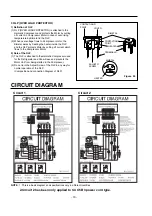
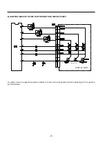
This description is made for GR-349, 389SQ. Please refer to overall PCB circuits for other models.
1 FUNCTION EXPOSITION
1) FUNCTION
(1) The refrigerator starts from optimum condition when electric power is first on. But the operation condition changes "Mid"
➝
"Mid/Max"
➝
"Max"
➝
"Min"
➝
"Min/Mid"
➝
"Mid" whenever pressing the FREEZE TEMP button.
(2) It returns to "Mid" conditions if power off and on again.
MICOM FUNCTION & PCB CIRCUIT EXPLANATION
- 17 -
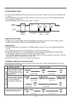
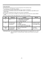
2) QUICK FREEZER
(1) Function to raise the freezing speed by operating the COMP successively. As pressing the QUICK FREEZE button, the
QUICK FREEZE LED is displayed. Then after 3 hours' successive operation of COMP, the QUICK FREEZING function
will be released.
(2) Defrosting During the QUICK FREEZING operates as follow.
When the QUICK FREEZING time is below 90 minutes, defrost and then operate the QUICK FREEZING for the
remaining time. When the QUICK FREEZING time is over 90 minutes, defrost and then operate the QUICK FREEZING
for 2 hours
(3) If QUICK FREEZE button is pressed during defrosting, the QUICK FREEZE LED is lit up. But the QUICK FREEZING
operates for 3 hours after 7 minutes from the end of defrosting.
(4) If VACATION button is pressed during the QUICK FREEZING, the QUICK FREEZING LED function is released.
(5) If power off during the QUICK FREEZING and power on again, the QUICK FREEZING function is released.
3) VACATION FUNCTION
(1) Function for Energy Saving. As pressing the VACATION button, the VACATION LED is displayed and this function is
operated.
(2) Freezer Compartment is not kept by compressor at the notch displayed but at -13¡C± differential.
(3) Defrosting and Fan control is same as normal operation.
(4) If QUICK FREEZE button is pressed during the VACATION FUNCTION, VACATION FUNCTION is released.
(5) If power off during the VACATION FUNCTION and power on again, the VACATION FUNCTION is released.
Summary of Contents for LRBP1031T
Page 30: ...2 REPLACEMENT PARTS LIST 30 ...
Page 31: ...3 PWB ASS Y DISPLAY AND PARTS LIST 31 ...
Page 32: ... 5 PWB circuit drawing The PWB circuit drawing may change without notice ...
Page 33: ... 33 ...
Page 36: ......

