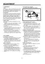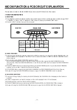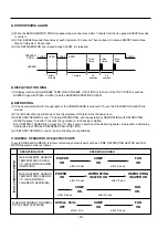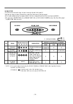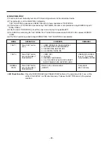
4 FAN AND FAN MOTOR
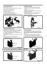
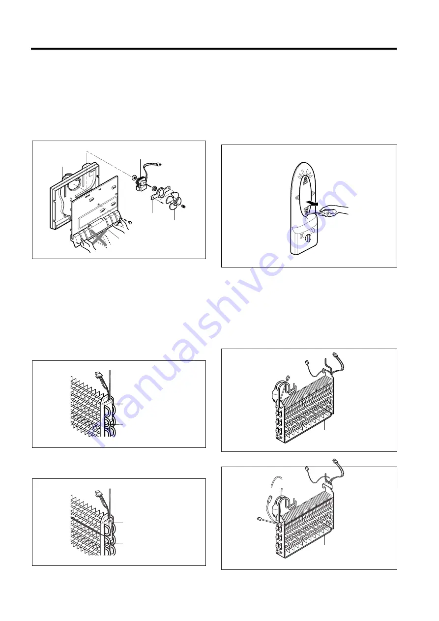
1) Remove freezer drawers.
2) Remove two cap, screws and loosen two screws in Grille Fan.
3) Pull out the Grille Fan and Shroud, F.
4) Disconnect the housing of lead wire.
5) Separate the Fan Assy.
6) Losse 2 screw fixed to the Bracket.
7) Pull out Shroud, F remove the Fan Motor Assy.
8) Separate the Motor Bracket and Rubber.
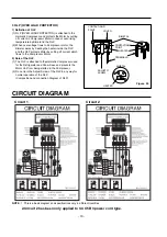
5 DEFROST CONTROL ASSY
Defrost Control Assy consists of Thermistor and Fuse, Melting.
Thermistor functions to defrost automatically and it is attached to
metal side of the Evaporator and senses temperature.
Fuse, Melting is a kind of safety device for preventing overheating
of the Heater when defrosting.
At the temperature of 72¡C, it stops the emission of heat from the
Heater.
1) Pull out the Shroud, F after removing the Grille.
2) Separate the connector connected with the Defrost Control
Assy and replace new one.
6 DAMPER CONTROL
1) Remove the Cover Lamp, R and loosen 2 screw.
2) Pull the Control Box, R and separate the lead wire
housing.
3) Remove the Cover Lamp, R.
4) Separate the Insulation Multi Duct and Control Box, R.
5) Disassemble the Knob.
6) Separate the Damper Control and Control Box, R.
7) Separate the Damper Control and Resistor.
8) Disconnect the lead wire.
7 HEATER, SHEATH
In this refrigerator, Heater, Sheath is used for defrosting
heater. During heating, the temperature of heater rises
about 300~500¡C. Therefore, be careful not to burn while
servicing.
1) After removing the Grille and Shroud, separate the
Heater, Sheath by disconnecting the connectors.
2) Exchanged Heater, Sheath and connected the housing.
REFRIGERATOR ROOM LAMP
GUIDE FAN
FAN
SHROUD
FAN MOTOR
GRILLE
Figure 13
Figure 14
Figure 11
Figure 12
- 8 -
Heater, Sheath
Fuse, Melting
Thermistor
Figure 14
Figure
A
B
12 B
A
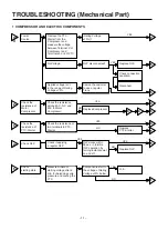
Note:
A
has been only applied to
Voltage 110-127V
area.
Fuse, Melting
Thermistor
Heater, Sheath
B has been only applied to
Voltage 220-240V
area.
Summary of Contents for LRBP1031T
Page 30: ...2 REPLACEMENT PARTS LIST 30 ...
Page 31: ...3 PWB ASS Y DISPLAY AND PARTS LIST 31 ...
Page 32: ... 5 PWB circuit drawing The PWB circuit drawing may change without notice ...
Page 33: ... 33 ...
Page 36: ......

