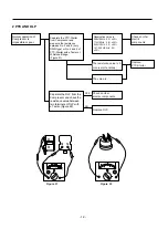
4) DOOR OPENING ALARM
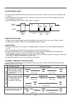
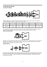
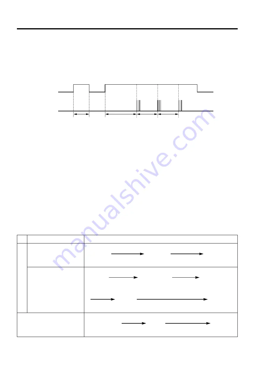
(1) When the REFRIGERATOR DOOR is opened and won't be closed after 1 minute from the its opened, BUZZER sounds
to notify it.
(2) At frist, BUZZER sounds three times at each intervals of 0.5 second. Then makes a 0.5 second ON/OFF alarm three
times at intervals of 30 seconds.
(3) If the REFRIGERATOR door closed during ALARM, it is released.
5) DISPLAY BUTTON RING
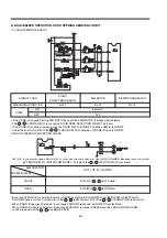
(1) If display function button(FREEZE TEMP, QUICK FREEZE, VACATION) of the front of the TOP COVER is pushed,
BUZZER rings with "DING~ DONG~"(See the BUZZER OPERATION CHECK)
6) DEFROSTING
(1) If the accumulated time for the operation of the COMPRESSOR is meet with 7 hours, the DEFROSTING HEATER is
started.
(2) The first defrosting is performed at 4 hours(compressor ON) later since the power is on.
(3) If DEFROST SENSOR is over 7¡C during DEFROSTING, end the operation of DEFROSTING with DEFROSTING
HEATER paused, And after 7 minutes, the operation for the freezing is started.
But, if DEFROST SENSOR is not reach to 7¡C after 2 hours' operation of the defrosting heater, it represents a defrosting
trouble.(See the TROUBLE REPRESENTING FUNCTION)
(4) If DEFROST SENSOR is short or open, defrosting is not performed.
7) ORDERLY OPERATION OF ELECTRIC PARTS
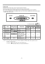
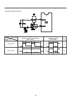
To avoid NOISE and DAMAGE, the items containing an electric parts such as COMP, DEFROSTING HEATER and FAN
MOTOR operate in order as follows.
- 18 -
CLOSE
OPEN
CLOSE
OPEN
CLOSE
BUZZER
within
1 minute
1 minute
30
seconds
30
seconds
three
times
three
times
three
times
FREEZER
DOOR
OPERATION STATE
OPERATION ORDER
WHEN DEFROST SENSOR
TEMPERATURE IS OVER
7¡C. (WHEN PURCHASING
OR MOVING)
WHEN DEFROST SENSOR
TEMPERATURE IS BELOW
7¡C. (WHEN POWER
FAILURE OR SERVICING)
WHEN RETURNING TO NORMAL
STATE FROM TEST MODE
POWER
COMP
FAN
ON
ON
ON
after 0.5 sec.
after 0.5 sec.
All Elec. Parts
COMP
FAN
OFF
ON
ON
after 7 min .
after 0.5 sec.
POWER
DEFROSTING
DEFROSTING
ON
HEATER ON
HEATER ON
after 0.5 sec.
after 10 sec.
COMP
FAN
ON
ON
after 0.5 sec.
after 0.5 sec.
WHEN PLUGGED A
T FIRST
Summary of Contents for LRBP1031T
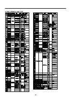
Page 30: ...2 REPLACEMENT PARTS LIST 30 ...
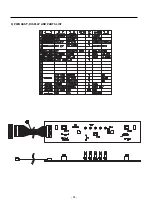
Page 31: ...3 PWB ASS Y DISPLAY AND PARTS LIST 31 ...
Page 32: ... 5 PWB circuit drawing The PWB circuit drawing may change without notice ...
Page 33: ... 33 ...
Page 36: ......

