


4-34
Copyright © 2008 LG Electronics. Inc. All right reserved.
Only for training and service purposes
LGE Internal Use Only
DESCRIPTION OF CIRCUIT
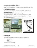
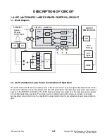
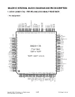
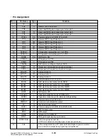
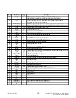
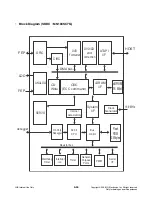
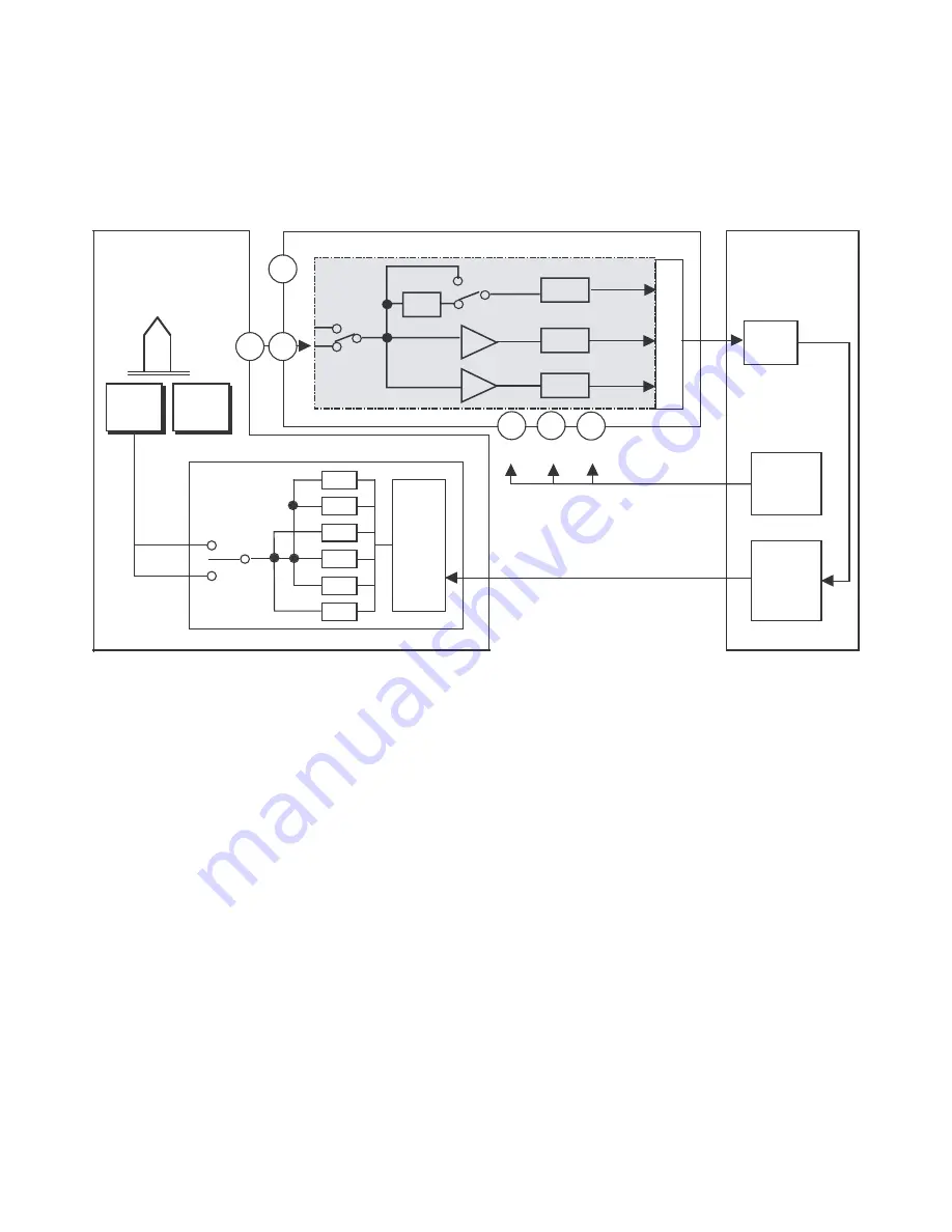
1. ALPC (AUTOMATIC LASER POWER CONTROL) CIRCUIT
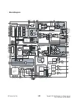
1-1. Block Diagram
1-2. ALPC (Automatic Laser Power Control) Circuit Operation
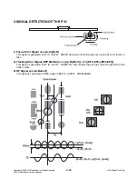
The ALPC block detects the laser output power of the front monitor. The power signal detected with the PD for
front monitor detection is input the voltage from the VPD pin(123Pin), the reference signal of the input signal is
input from the VREFPD pin(124Pin). The ALPC block generates the singals from the input laser power signals
in the following detection systems. This block has four detection paths:All average value path, multi pulse
average/peak value detection path, erase/bottom value detection path, space/playback power value detection
path.
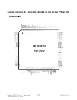
MN103SC7G
Write
Strategy
LIC201
LPM101
Optical
Pick-up
HOP-7232TL
LD
PD
LDD
Serial
I/F
D/A
D/A
D/A
D/A
D/A
D/A
M
P
X
LIC101
AN22117A
APC
19
A/D
ADSC
S/H
Signal
FM
123
FPD
124
VREFPD
40
41
42
SH1
SH2
SH3
VGA
LPF
Ave
Erase
Space
VGA
S/H2
S/H3
S/H1