


-43-
4. Trouble Shooting
4.1 Power On Trouble
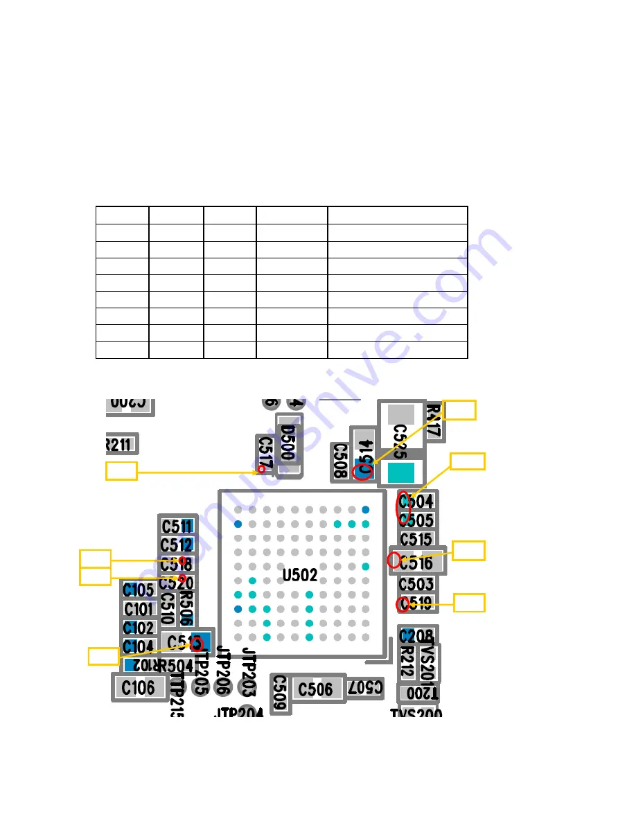
4.1.1 Test Point
Check Points :
‐
Battery Voltage(Need to over 3.31V)
‐
Power-On key detection(PWRON signal)
‐
Outputs of LDOs by U502
Name
Output
TP
Component
Describe
Vcore
1.8V
TP1
C504 & C505 Power on check
VDD
2.8V
TP2
C513
Power on check
AVDD
2.8V
TP3
C514
Power on check
VMEM
1.8V
TP4
C516
Power on check
VSIM
1.8V / 3V TP5
C517
No detect SIM check point
VRTC
1.5V
TP6
C518
Power on check
VUSB
3.3V
TP7
C519
USB fail check point
VIB
3.2V
TP8
C520
Vibrator fail check point
PCB Placement
TP1
TP2
TP3
TP4
TP5
TP6
TP7
TP8
Summary of Contents for GB175
Page 1: ...1 GB175 Service Manual LG Electronics ...
Page 16: ... 16 3 TECHNICAL BRIEF 3 1 Digital Main Processor Figure 3 1 1 MT6225 FUNCTIONAL BLOCK DIAGRAM ...
Page 22: ... 22 Figure 3 1 2 MT6225 BLOCK DIAGRAM ...
Page 28: ... 28 3 5 Memory Module PF38F4050M0Y0CG Figure 3 5 1 PF38F4050M0Y0CG FUNCTIONAL BLOCK DIAGRAM ...
Page 30: ... 30 ...
Page 31: ... 31 ...
Page 33: ... 33 ...
Page 36: ... 36 Figure 3 9 2 IM152FBN5A Block Diagram ...
Page 45: ... 45 4 2 SIM Card Trouble 4 2 1 Test Point 4 2 2 Circuit Diagram VSIM VSIM ...
Page 48: ... 48 4 4 Keypad Trouble 4 4 1 Test Point 4 4 2 Circuit Diagram Key pad Top View ...
Page 49: ... 49 4 4 3 Checking Flow Change Metal Dome Start Change PCB NG OK Check Metal Dome ...
Page 50: ... 50 4 5 RTC Trouble 4 5 1 Test Point 4 5 2 Circuit Diagram XIN XOUT VRTC XIN XOUT ...
Page 51: ... 51 XIN XOUT ...
Page 53: ... 53 4 6 Key Backlight Trouble ...
Page 54: ... 54 4 6 1 Test Point 4 6 2 Circuit Diagram TP8 TP8 TP9 TP9 ...
Page 56: ... 56 4 7 LCM Backlight Trouble 4 7 1 Test Point TP11 TP10 TP12 ...
Page 58: ... 58 4 8 LCM Trouble 4 8 1 Test Point 4 8 2 Circuit Diagram TP13 TP14 TP14 TP13 ...
Page 60: ... 60 4 9 Microphone Trouble 4 9 1 Test Point 4 9 2 Circuit Diagram TP15 TP15 ...
Page 62: ... 62 4 10 Receiver Trouble 4 10 1 Test Point 4 10 2 Circuit Diagram TP16 TP17 TP16 TP17 ...
Page 69: ... 69 4 13 Charging Trouble 4 13 1 Test Point 4 13 2 Circuit Diagram TP31 TP31 ...
Page 73: ... 73 4 15 TRX PAM 4 15 1 Test Point TP38 TP37 TP34 TP35 TP39 TP36 TP40 ...
Page 74: ... 74 4 15 2 Circuit Diagram TP34 TP35 TP36 TP37 TP41 TP40 TP39 ...
Page 78: ... 78 5 DOWNLOAD 5 1 Download setup ...
Page 87: ... 87 6 BLOCK DIAGRAM ...
Page 88: ... 88 7 CIRCUIT DIAGRMA ...
Page 89: ... 89 ...
Page 90: ... 90 ...
Page 91: ... 91 ...
Page 92: ... 92 ...
Page 93: ... 93 ...
Page 94: ... 94 ...
Page 95: ... 95 ...
Page 97: ... 97 8 2 BGA PIN Check of Memory PF38F4050M0Y0CG PF38F4050M0Y0CG U200 BGA use BGA non use ...
Page 98: ... 98 8 3 BGA PIN Check of PMIC MT6318 MT6318 U502 BGA use BGA non use ...
Page 99: ... 99 9 PCB LAYOUT TOP J401 Receiver PAD No receiver ...
Page 103: ... 103 Work Flow ...
Page 105: ... 105 11 CALIBRATION 11 1 Test Equipment set up ...
Page 109: ... 109 ...
Page 111: ... 111 Execute Measurement Automation to check equipment address Choose Devices and Interfaces ...
Page 113: ... 113 Setup your CMU Base GPIB address and power supply address ...
Page 114: ... 114 ATE Tool system setting Execute MTK _ ate demo Press Report System button ...
Page 115: ... 115 Setting your equipment Setting your power supply type Choose your Power Supply Type ...
Page 119: ... 119 How to setup your test report location Choose my computer Choose C disk ...
Page 120: ... 120 Choose program files Choose Program Files ATE Tools KP199_KP320_KM330_KM335_KC530 file ...
Page 121: ... 121 Setup new file and leave the window Execute MTK _ ate demo ...
Page 122: ... 122 Press Report System button Press select test report location ...
Page 123: ... 123 Choose your setup report Press Done ...
Page 124: ... 124 Setup finish When you finish the setup then you press save change icon ...
Page 125: ... 125 Press Configuration choose Cal Setting Setting your cable loss ...
Page 126: ... 126 Press Done to save Press Configuration choose Final setting ...
Page 128: ... 128 If you want calibration you can press initial calibration Press Calibration Test ...
Page 129: ... 129 Key in your phone bar Code Press your phone of power on key and Start calibration ...
Page 130: ... 130 Calibration is ok and will show PASS You can see the test report ...
Page 131: ... 131 If you want final test you can press initial final test ...
Page 132: ... 132 Press RF Final test ...
Page 133: ... 133 1 Handset to insert SIM card 2 Key in bar code or IMEI number 3 power on handset ...
Page 134: ... 134 ATE start final test ...
Page 135: ... 135 If ATE test finish ATE will show pass ...
Page 136: ... 136 You can see the test report ...
Page 137: ... 137 If you want initial cal and final test you can press initial cal and final test ...
Page 138: ... 138 Press Cal Final ...
Page 139: ... 139 1 Handset to insert SIM card 2 Key in bar code or IMEI number 3 Power on handset ...
Page 140: ... 140 Start calibration ...
Page 141: ... 141 Calibration finish and power on handset again ...
Page 142: ... 142 Start final test ...
Page 143: ... 143 Finish Cal Final test ...
Page 144: ... 144 Ate show the test report ...
Page 147: ... 147 4 Install Process press Next 5 Install Process press Next 6 Install Process ...
Page 148: ... 148 7 Install Process press Finish ...
Page 155: ... 155 13 EXPLODED VIEW REPLACEMENT PART LIST 13 1 Exploded view ...
Page 156: ... 156 Ass y exploded view ...