


-34-
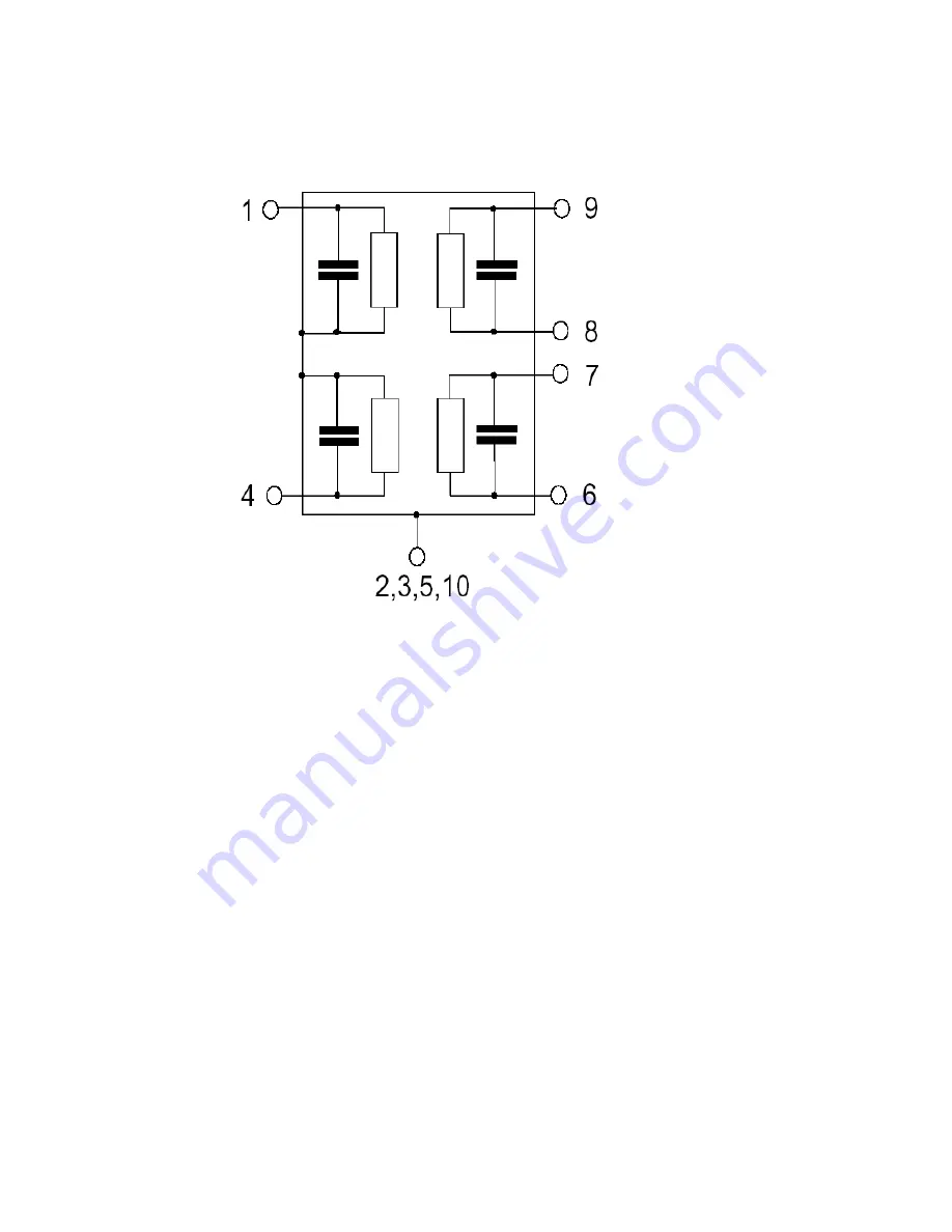
3.7 Antenna Switch Module (B9308)
Application
Low-loss 2in1 RF filter for mobile telephone GSM 900 and GSM 1800 systems, receive path
(Rx)
Usable passband:
Filter 1 (GSM 1800): 75 MHz
Filter 2 (GSM 900): 35 MHz
Unbalanced to balanced operation for both filters
Very low insertion attenuation
Low amplitute ripple
Impedance transformation from 50 W to 150 W for both filters
Suitable for GPRS class 1 to 12
Pin configuration
1 Input [Filter 1]
4 Input [Filter 2]
6,7 Output, balanced [Filter 2]
8,9 Output, balanced [Filter 1]
2,3,5,10 Case-ground
Summary of Contents for GB175
Page 1: ...1 GB175 Service Manual LG Electronics ...
Page 16: ... 16 3 TECHNICAL BRIEF 3 1 Digital Main Processor Figure 3 1 1 MT6225 FUNCTIONAL BLOCK DIAGRAM ...
Page 22: ... 22 Figure 3 1 2 MT6225 BLOCK DIAGRAM ...
Page 28: ... 28 3 5 Memory Module PF38F4050M0Y0CG Figure 3 5 1 PF38F4050M0Y0CG FUNCTIONAL BLOCK DIAGRAM ...
Page 30: ... 30 ...
Page 31: ... 31 ...
Page 33: ... 33 ...
Page 36: ... 36 Figure 3 9 2 IM152FBN5A Block Diagram ...
Page 45: ... 45 4 2 SIM Card Trouble 4 2 1 Test Point 4 2 2 Circuit Diagram VSIM VSIM ...
Page 48: ... 48 4 4 Keypad Trouble 4 4 1 Test Point 4 4 2 Circuit Diagram Key pad Top View ...
Page 49: ... 49 4 4 3 Checking Flow Change Metal Dome Start Change PCB NG OK Check Metal Dome ...
Page 50: ... 50 4 5 RTC Trouble 4 5 1 Test Point 4 5 2 Circuit Diagram XIN XOUT VRTC XIN XOUT ...
Page 51: ... 51 XIN XOUT ...
Page 53: ... 53 4 6 Key Backlight Trouble ...
Page 54: ... 54 4 6 1 Test Point 4 6 2 Circuit Diagram TP8 TP8 TP9 TP9 ...
Page 56: ... 56 4 7 LCM Backlight Trouble 4 7 1 Test Point TP11 TP10 TP12 ...
Page 58: ... 58 4 8 LCM Trouble 4 8 1 Test Point 4 8 2 Circuit Diagram TP13 TP14 TP14 TP13 ...
Page 60: ... 60 4 9 Microphone Trouble 4 9 1 Test Point 4 9 2 Circuit Diagram TP15 TP15 ...
Page 62: ... 62 4 10 Receiver Trouble 4 10 1 Test Point 4 10 2 Circuit Diagram TP16 TP17 TP16 TP17 ...
Page 69: ... 69 4 13 Charging Trouble 4 13 1 Test Point 4 13 2 Circuit Diagram TP31 TP31 ...
Page 73: ... 73 4 15 TRX PAM 4 15 1 Test Point TP38 TP37 TP34 TP35 TP39 TP36 TP40 ...
Page 74: ... 74 4 15 2 Circuit Diagram TP34 TP35 TP36 TP37 TP41 TP40 TP39 ...
Page 78: ... 78 5 DOWNLOAD 5 1 Download setup ...
Page 87: ... 87 6 BLOCK DIAGRAM ...
Page 88: ... 88 7 CIRCUIT DIAGRMA ...
Page 89: ... 89 ...
Page 90: ... 90 ...
Page 91: ... 91 ...
Page 92: ... 92 ...
Page 93: ... 93 ...
Page 94: ... 94 ...
Page 95: ... 95 ...
Page 97: ... 97 8 2 BGA PIN Check of Memory PF38F4050M0Y0CG PF38F4050M0Y0CG U200 BGA use BGA non use ...
Page 98: ... 98 8 3 BGA PIN Check of PMIC MT6318 MT6318 U502 BGA use BGA non use ...
Page 99: ... 99 9 PCB LAYOUT TOP J401 Receiver PAD No receiver ...
Page 103: ... 103 Work Flow ...
Page 105: ... 105 11 CALIBRATION 11 1 Test Equipment set up ...
Page 109: ... 109 ...
Page 111: ... 111 Execute Measurement Automation to check equipment address Choose Devices and Interfaces ...
Page 113: ... 113 Setup your CMU Base GPIB address and power supply address ...
Page 114: ... 114 ATE Tool system setting Execute MTK _ ate demo Press Report System button ...
Page 115: ... 115 Setting your equipment Setting your power supply type Choose your Power Supply Type ...
Page 119: ... 119 How to setup your test report location Choose my computer Choose C disk ...
Page 120: ... 120 Choose program files Choose Program Files ATE Tools KP199_KP320_KM330_KM335_KC530 file ...
Page 121: ... 121 Setup new file and leave the window Execute MTK _ ate demo ...
Page 122: ... 122 Press Report System button Press select test report location ...
Page 123: ... 123 Choose your setup report Press Done ...
Page 124: ... 124 Setup finish When you finish the setup then you press save change icon ...
Page 125: ... 125 Press Configuration choose Cal Setting Setting your cable loss ...
Page 126: ... 126 Press Done to save Press Configuration choose Final setting ...
Page 128: ... 128 If you want calibration you can press initial calibration Press Calibration Test ...
Page 129: ... 129 Key in your phone bar Code Press your phone of power on key and Start calibration ...
Page 130: ... 130 Calibration is ok and will show PASS You can see the test report ...
Page 131: ... 131 If you want final test you can press initial final test ...
Page 132: ... 132 Press RF Final test ...
Page 133: ... 133 1 Handset to insert SIM card 2 Key in bar code or IMEI number 3 power on handset ...
Page 134: ... 134 ATE start final test ...
Page 135: ... 135 If ATE test finish ATE will show pass ...
Page 136: ... 136 You can see the test report ...
Page 137: ... 137 If you want initial cal and final test you can press initial cal and final test ...
Page 138: ... 138 Press Cal Final ...
Page 139: ... 139 1 Handset to insert SIM card 2 Key in bar code or IMEI number 3 Power on handset ...
Page 140: ... 140 Start calibration ...
Page 141: ... 141 Calibration finish and power on handset again ...
Page 142: ... 142 Start final test ...
Page 143: ... 143 Finish Cal Final test ...
Page 144: ... 144 Ate show the test report ...
Page 147: ... 147 4 Install Process press Next 5 Install Process press Next 6 Install Process ...
Page 148: ... 148 7 Install Process press Finish ...
Page 155: ... 155 13 EXPLODED VIEW REPLACEMENT PART LIST 13 1 Exploded view ...
Page 156: ... 156 Ass y exploded view ...