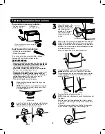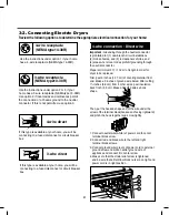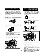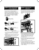
14
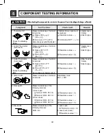
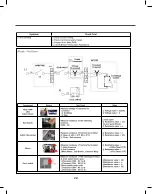
When checking the component, be sure to turn the power off, and do voltage discharge sufficiently.
!
CAUTION
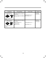
1. Thermal cut off
Check Top Marking:
N140
Measure resistance of terminal
to terminal
Open at 284
(140
Same shape as outlet thermostat.
If thermal fuse is open must
be replaced
Resistance value
Heater case-
Safety
Electric type
2. Hi limit Thermostat
(Auto reset)
Measure resistance of terminal
to terminal
Open at 257
(125
Close at 221
(94
Resistance value
Heater case -
Hi limit
Electric type
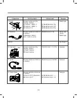
3. Outlet Thermostat
( Auto reset)
Check Top Marking:
N85
Measure resistance of terminal
to terminal
Open at 185
(85
Close at 167
(75
Same shape as thermal cut off.
Resistance value
Blow housing -
Safety
Electric type
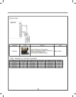
4. Lamp holder
Measure resistance of terminal
to terminal
Resistance value:
80 ~ 100
6. Idler switch
Measure resistance of the
following terminal:
COM - NC
1. Lever open
2. Lever push (close)
Resistance value
5. Door switch
Measure resistance of the
following terminal
1) Door open
Terminal: COM - NC (1-3)
Terminal: COM - NO (1-2)
2) Door closed
Terminal: COM - NC (1-3)
Terminal: COM - NO (1-2)
Resistance value
Resistance value
5
COMPONENT TESTING INFORMATION
Summary of Contents for DLE3170W
Page 10: ...10 1 2 5 cm 3 8 9 cm Option 1 0 ...
Page 18: ...18 GN YL 3 WIRE SYSTEM EARTH 4 WIRE SYSTEM X1 X2 CN11 CN11 X1 X2 7 WIRING DIAGRAM ...
Page 23: ...23 8 4 Troubleshooting with Error ...
Page 24: ...24 ...
Page 25: ...25 ...
Page 26: ...26 ...
Page 27: ...27 ...
Page 28: ...28 ...
Page 29: ...29 ...
Page 30: ...30 ...
Page 35: ...35 Test 2 Thermistor Test Measure with Power Off ...
Page 36: ...36 Test 3 Motor Test ...
Page 37: ...37 6AIJ ...
Page 38: ...38 Test 5 Door switch test ...
Page 39: ...39 Test 6 Heater switch test Electric Type ...
Page 40: ...40 ᅐ Test 7 GAS Valve test Gas Type ...
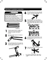
Page 47: ...47 DRYER EXHAUST CHANGE 1 2 3 4 5 Note ...
Page 50: ...12 EXPLODED VIEW 50 12 1 Control Panel and Plate Assembly A210 A211 A130 A120 A140 A110 ...

