Caution
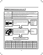
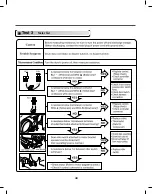
Trouble Symptom
Measurement Condition
1. Power Connection
2. Status Mode Of The Connection
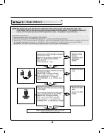
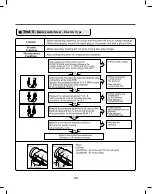
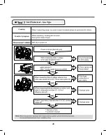
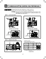
When measuring power, be sure to wear insulated gloves to avoid an electric shock.
With Dryer Power On; Connector linked to Controller.
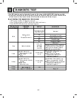
High
Mid High
Medium
High
Mid High
Medium
Tab Relay 1
Tab Relay 1
Burner Remark
Tab Relay 2
Heater 1
Heater 2
Remark
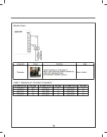
Connector Housing
Black
Yellow wire
Blue wire
Black wire
Black wire
Connector Housing Tap relay 1
Connector Housing Tap relay 2
Check the Matching color Between
Harness wire and tap relay.
(Black Housing – Black tap relay)
Check the Matching color Between
Harness wire and tap relay.
(White Housing – White tap relay)
White
Low
Extra Low
Low
Extra Low
on
on
on
on
on
O O
O O
on
off
off
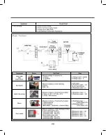
Temperature Control below 68
ᴦ
4
Turn on Heater1 and Heater2.
Temperature Control below 52
ᴦ
4
Only Turn on Heater1.
Temperature Control below 70
ᴦ
4
Turn on Burner
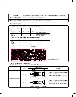
PCB ASSEMBLY LAYOUT
Temperature Control below 47
ᴦ
4
Turn on Burner
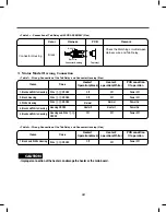
< Table1 > : Connection of the tap relay with Heater (Electric)
< Table 2 > : Connection of the Tab Relay with Burner (Gas)
< Table1 > : Connection of tap relay with the PCB ASSEMBLY Electric
Color
Remark
Connection
Harness
PCB
Check the Tab Relays Connection properly.
33
Summary of Contents for DLE3170W
Page 10: ...10 1 2 5 cm 3 8 9 cm Option 1 0 ...
Page 18: ...18 GN YL 3 WIRE SYSTEM EARTH 4 WIRE SYSTEM X1 X2 CN11 CN11 X1 X2 7 WIRING DIAGRAM ...
Page 23: ...23 8 4 Troubleshooting with Error ...
Page 24: ...24 ...
Page 25: ...25 ...
Page 26: ...26 ...
Page 27: ...27 ...
Page 28: ...28 ...
Page 29: ...29 ...
Page 30: ...30 ...
Page 35: ...35 Test 2 Thermistor Test Measure with Power Off ...
Page 36: ...36 Test 3 Motor Test ...
Page 37: ...37 6AIJ ...
Page 38: ...38 Test 5 Door switch test ...
Page 39: ...39 Test 6 Heater switch test Electric Type ...
Page 40: ...40 ᅐ Test 7 GAS Valve test Gas Type ...
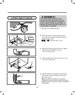
Page 47: ...47 DRYER EXHAUST CHANGE 1 2 3 4 5 Note ...
Page 50: ...12 EXPLODED VIEW 50 12 1 Control Panel and Plate Assembly A210 A211 A130 A120 A140 A110 ...


