44
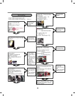
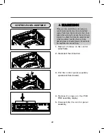
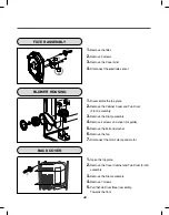
CONTROL PANEL ASSEMBLY
1.
Remove 2 screws on the control
panel frame.
2.
Disconnect the connectors.
3.
Pull the control panel assembly
upward and then forward.
4.
Remove 8 screws on the PCB
PCB) assembly, display.
5.
Disassemble the control panel
assembly.
W
WA
AR
RN
NIIN
NG
G!!
When you disassemble the control panel, be
sure to disconnect the dryer from its electrical
supply. Protect your hands and arms from sharp
edges when working. To reduce the risk of injury
to persons, adhere to all industry recommended
safety procedures including the use of long
sleeved gloves and safety glasses. Failure to do
this could lead to a serious injury.
Summary of Contents for DLE3170W
Page 10: ...10 1 2 5 cm 3 8 9 cm Option 1 0 ...
Page 18: ...18 GN YL 3 WIRE SYSTEM EARTH 4 WIRE SYSTEM X1 X2 CN11 CN11 X1 X2 7 WIRING DIAGRAM ...
Page 23: ...23 8 4 Troubleshooting with Error ...
Page 24: ...24 ...
Page 25: ...25 ...
Page 26: ...26 ...
Page 27: ...27 ...
Page 28: ...28 ...
Page 29: ...29 ...
Page 30: ...30 ...
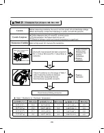
Page 35: ...35 Test 2 Thermistor Test Measure with Power Off ...
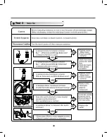
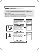
Page 36: ...36 Test 3 Motor Test ...
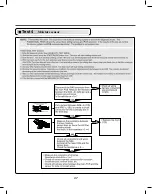
Page 37: ...37 6AIJ ...
Page 38: ...38 Test 5 Door switch test ...
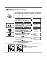
Page 39: ...39 Test 6 Heater switch test Electric Type ...
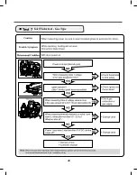
Page 40: ...40 ᅐ Test 7 GAS Valve test Gas Type ...
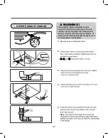
Page 47: ...47 DRYER EXHAUST CHANGE 1 2 3 4 5 Note ...
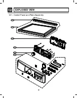
Page 50: ...12 EXPLODED VIEW 50 12 1 Control Panel and Plate Assembly A210 A211 A130 A120 A140 A110 ...

