57
November 2009 50PQ30 Plasma
Y
Y
-
-
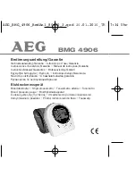
SUS Board P209 (Top Connector) Explained
SUS Board P209 (Top Connector) Explained
P209
FG5V (+5V F) measured
from Pins 4 or 5 to
Floating Gnd
Pins 1~3, 6 or 11
P209 Pins 7, 8, 9, and 10 are Logic Signals
from the Control board routed through the
Y-SUS to the Y-Drive upper.
Between the Y-Drive upper and lower is
P209, P108 which carries the Y-Drive (Scan)
signals from the lower to the upper.
Y-Drive Upper
Board
Y-SUS Board
Top Connector P209
P109
11) Ground (F)
10) DATA
9) OC1
8) STB
7) CLK
6) Ground (F)
5) 5V VF
4) 5V Vf
3) Ground (F)
2) Ground (F)
1) Ground (F)
c
FL101