8
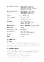
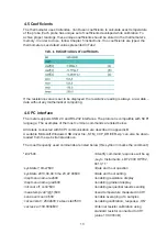
Pt-100 measurement current
Pt-100 self heating power
Supply
Power consumption
Fuses
Connectors
RS-232 parameters
USB standard
Communication protocol
Temperature range
Dimension
weight
LDT 2000 OPT x1, x1: 0,23mA ±10%;
LDT 2000 OPT x2, x2: 1mA ±10%;
LDT 2000 OPT x3, x3: 1mA ±10% with stand by
current in non-active channel
LDT 2000 OPT x1, x1 : 5,8μW for 0 °C
LDT 2000 OPT x2, x2: 101μW for 0 °C
LDT 2000 OPT x3, x3: 101μW for 0 °C
85-250VAC, 45...65 Hz
8VA max. 4VA typically
2x SLOW 1A 250V; 5x20mm
• Supply 230V – IEC C14
• USB B connector – USB interface
• DB9 -RS-232 interface
ABaud rate: 9600; data bits: 8; parity:no; stop bits:1
USB 2.0
SCPI compatible
storage:-10°C...+60 °C;
usage: 10°C...40 °C, non-condensing
271 x 280 x 102,6 mm
ca. 1,5 kg
3. OPERATION
3.1 Safety
The LDT 2000 temperature meter is a device designed for laboratory, indoor use. It is
powered from 85 to 250V line, therefore the user should work with respect to all precau-
tions related to operating with mains powered equipment. The mains socket should always
have working grounding path!
3.2 Preparation to work
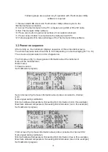
1. Connect one or two (as needed) probes to the sockets on the thermometer’s front panel.
Please keep in mind that each channel has its own calibration coefficients and probe’s
plug must be placed in proper, signed socket. A mistake will result in wrong temperature
readings
2. Connect the instrument to the power line
3. Turn on the instrument by pressing POWER switch
4. Read the messages displayed by the instrument (chapter 3.3)
5. Wait until self calibration sequence reaches 100%
6. The thermometer is now ready to stand- alone operation
Summary of Contents for LDT 2000
Page 1: ...1 LDT 2000 PRECISION THERMOMETER MANUAL...
Page 14: ...14 5 Typical performance of the thermometer...
Page 15: ...15...
Page 16: ...16...
Page 17: ...17...
Page 43: ......
Page 44: ......


