background image

34

To measure temperature on second channel:

1) :CONF:TEMP:VAL (@2)

2) :CONF:TEMP (@2)

3) :CONF (@2)

Measurement of gradient or resistance, requires providing full path of commands. To mea-

sure gradient on first channel, configure using one of following commands:

1) :CONF:TEMP:GRAD (@1)

2) :CONF:TEMP:GRAD.

Measurement of Pt100 probe’s resistance for both channels can be setup using:


:CONF:TEMP:RES (@1,2)

Measurement of temperature difference between channels 2 and 1 can be setup using:


:CONF:TEMP:DIFF (@2,1)

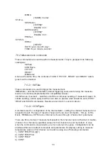
7.6.2.3 :CONFigure?

This command can be used to read thermometer’s current configuration. It returns a string, 

formatted with the same structure, as the one used for configuration. For example, if ther

-

mometer is configured to read temperature value of first channel, returned string will be:


TEMP:VAL (@1)

and for resistance measurement on second channel:


TEMP:RES (@2).

Sending this command after connecting to thermometer, allows orientation on which pro-

bes are connected to the device.

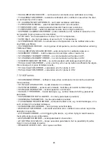
7.6.2.4 Result readout commands :FETCh? and :READ?

These commands read the result of currently configured measurement. :FETC? reads the 

last result stored in thermometer’s memory, :READ? starts the measurement and then 

sends back the result. :READ? can be treated as a sequence of following commands:

1) :INIT

2) :FETC?

Both commands need proper configuration of measurement first. It can be set using 

:CONFigure or :MEASure command. For FETC? command, exemplary valid execution can 

consist of following sequence:

1) :CONF:TEMP:VAL (@1)

2) :INIT

3) FETC?

For :READ? command:

1) :CONF:TEMP:VAL (@1)

2) :READ?

Commands above must not be called directly one after another. They just need to be called 

between last reset of the device, and using the read commands. In such way, no error is 

notified.

Calling read commands without any parameters or sub-commands, results in sending 

values according to last configuration. It is also possible to read another parameters of the 

same measurement. While measuring the temperature of certain channel, probe’s gradient 

and resistance can also be read. During double-channel measurement, each parameter’s 

value can be achieved.

Read command must be called in order to do that, including specific sub-commands and 

list of channels, similarily as in :CONFigure command. While tempting to read an unmea

-

sured value, error is notified.

Measurement result is sent back after filling the sample buffers, which can take up maxi

-

mum of 25 seconds. Because non-holding mode of command execution is used, during 

this time the thermometer won’t react to any other commands.

Summary of Contents for LDT 2000

Page 1: ...1 LDT 2000 PRECISION THERMOMETER MANUAL...

Page 2: ...f the described products The document may contain technical inaccuracies and typographical errors The content will be revised on a regular basis These changes will be implemented in later versions The...

Page 3: ...6 Internal battery 3 7 Calibration period 3 8 Calibration period 4 Advanced user information 4 1 Block diagram 4 2 Probes 4 3 Extender 4 4 Resistance calibration 4 5 Coefficients 4 6 PC interface 5 T...

Page 4: ...Default commands 7 3 Status registers 7 3 1 STB status register 7 3 2 Events register ESR 7 3 3 Operation register OPER 7 3 4 Reliability register QUES 7 3 5 Errors queue 7 3 6 Mask registers 7 4 Com...

Page 5: ...CALibration calibration commands 7 6 6 1 ALL autocalibration 7 6 6 2 SECure calibration unlocking 7 6 6 3 RESistance resistance measurement calibration 7 6 6 4 CHannel 1 and CHannel 2 probes calibrati...

Page 6: ...ieve optimum functioning of the equip ment 1 2 General safety Instructions The LDT 2000 temperature meter is a device designed for laboratory indoor use It is powered from 85 to 250V line therefore th...

Page 7: ...eans of Current Reversal technique The autocalibration sequence is a background task performed continuously The LDT 2000 has been designed to make operating as simple as possible An advanced configura...

Page 8: ...102 6 mm ca 1 5 kg 3 OPERATION 3 1 Safety The LDT 2000 temperature meter is a device designed for laboratory indoor use It is powered from 85 to 250V line therefore the user should work with respect t...

Page 9: ...ts about 40s to 120s depending on used averaging N 1 to 10 The screens are presented in order of apperance The first screen fig 1 shows general information about the instrument Name of the manufacture...

Page 10: ...vailable for Microsoft Windows Operating Systems The software supports 1 Monitoring measured parameters in time domain using adjustable scale display 2 Data acqiusiton and recording Advanced controlls...

Page 11: ...ry 12 months if the working temperature is T 200 C 4 Advanced user information 4 1 Block diagram The LDT 2000 thermometer is a microprocessor based meter which accurately measu res probe s resistance...

Page 12: ...is preferred Using long extender in industrial environment with very high electromag netic interferences level can increase the measurement noise 4 4 Resistance calibration In case of performing resi...

Page 13: ...d below All details connected with SCPI communication are described in appendix B A suitable Microsoft Windows USB driver file STM_VCP_DRIVER zip can also be down loaded from the web site listed above...

Page 14: ...14 5 Typical performance of the thermometer...

Page 15: ...15...

Page 16: ...16...

Page 17: ...17...

Page 18: ...nd requirements To start the installation run setup exe file and confirm to deploy the program After quick setup utility runs for the first time Later it will be available from desktop shortcut fig 13...

Page 19: ...can be chosen by expanding combo list next to CONNECT button and selecting device s serial number After pressing the mentioned button communication with thermometer will initialize and other functions...

Page 20: ...since the start of collection it grows to the right The chart can store up to 24 hours of samples and after that time the chart stops receiving further data The chart however can be reset any time by...

Page 21: ...ive keyboard up down keys or with mouse wheel if exists The chart can be copied to clipboard as a bitmap and used e g as a report in a document This can be done by pressing Copy to clipboard button lo...

Page 22: ...this field 3 Mark End field 4 As in p 2 input date time this time adequate to 3th of September half past 10 PM 5 Set Interval s field to 1800 30 times 60 seconds 6 Press START button After completing...

Page 23: ...the resistance of the probe s sensor NONE additional results are not displayed for clearance Average count sets from 1 to 10 the amount of samples that would be averaged to cal culate current level A...

Page 24: ...cates last calibration date for probe This field is filled automaticcaly during calibration R0 probe s resistance at 0 C Coeffs A B C coefficients for Callendar Van Dusen equation for calculating resi...

Page 25: ...the buttons attached to each row of the table It is reccomended to export certain probe s data to a file for troubleshooting The Calibration tab allows to modify probe s memory content and to calibrat...

Page 26: ...l word Therefore MEAS MEASURE but also MEASUR or MEASURE1 will execute the same command Using mnemonics is recommended since not all full names are properly recog nized Character case in command is ig...

Page 27: ...means the device should send back the temperature value If no response comes back it means an error had ocurred 7 2 6 Parameters Both plain commands as well as queries can accept parameters These can...

Page 28: ...ogues by default therefore to enter any ca talogue its name must appear in message Per example then to read temperature s value gradient and resistance it can be commonly achieved by sending MEAS TEMP...

Page 29: ...er failure always 0 7 3 3 Operation register OPER Sixteen bit register of currently executed operations Specific bit is set while an operation continues and is zeroed after it passes Only three bits a...

Page 30: ...f any characters except the special ones Maximum length is 15 characters 7 4 5 Channels list Used for setting the amount and numbers of measured channels It implements somewhat specific format It is w...

Page 31: ...int sets the mask of status register STB to decimal value passed as parame ter SRE reads the value of status register mask STB STB reads the value of status register STB afterwards the register is re...

Page 32: ...IN TMAX CALibration ALL ALL SECure STATe boolean password RESistance VALue R value VALue R value DATE CH1 CHannel1 R0 R0 value COEFficient A B C PCORrection a0 a1 a2 NCORrection a0 a1 a2 TMIN Tmin val...

Page 33: ...alues To initiate sending certain query must be sent also to precise what should be sent FETC READ and MEAS commands Results are sent with second interval 7 6 2 2 CONFigure Command used for configurat...

Page 34: ...urement and then sends back the result READ can be treated as a sequence of following commands 1 INIT 2 FETC Both commands need proper configuration of measurement first It can be set using CONFigure...

Page 35: ...a query for this command will result in sending name of a presently used scale After switching off the thermometer stores scale that had been used recently 7 6 4 INPut measurement circuit configuratio...

Page 36: ...efault command checking exceeding of limit can be done in one of two ways 1 SENS OVER CH1 TMIN 2 OVER CH1 TMIN Over range condition is set if within the following 20 measurements of temperature over 1...

Page 37: ...tor Sending the same command as a query CAL RES VAL R value will prompt the device to return calibration s state zero is successful or error number in case of failure Because the calibration itself la...

Page 38: ...ing memory in a first channel of the probe can be done in two ways 1 MEM CLEar NAME CH1 2 CLEar NAME CH1 To prevent accidental deletion of data before attempting to erase the memory the user must firs...

Page 39: ...ode from queue After the readout the error is removed from queue Full list of notified errors is described in separate chapter 7 6 10 2 DATE year month day Setting and reading of current date from the...

Page 40: ...METER MEMORY ERROR no communication with analogue board memory 150 CALCULATION ERROR error occurring when using certain coefficients the algori thm is divergent or gives forbidden results 151 CALCULA...

Page 41: ..._____________________ _____________________________________________________________________________ _____________________________________________________________________________ ______________________...

Page 42: ...CENTRAL OFFICE LEYRO INSTRUMENTS SL Avda Somosierra 24 28703 San Sebasti n de los Reyes Madrid Tel 34 912 835 502 info leyro net www leyroinstruments com...

Page 43: ......

Page 44: ......

Reviews: