8
6. Now locate all the component parts, which make up the TSG mounting plate
assembly, reference page 9 to identify them. The centerline of the two mounting
plates should be spaced at least 30” apart. Hold parts up to locate holes
required in truck chassis and mark gussets and plates for trimming.
7. Lower floor jack and let gate swing out of the way. Drill 9/16” holes through
chassis to attach both mounting plates. Bolt plates in place using hardware
supplied. Lift trunion tube of gate back in position.
8. Now tack weld the gussets and support plate to the mounting plate and trunion
tube. Welds must be strong enough to support the gate without a load on the
platform.
9. Locate a suitable spot to mount the power unit enclosure. Use the two brackets
and shims supplied. Refer to the sketch on page 10. Connect the hydraulic
hose and plastic tubing from the lift cylinder to the power unit.
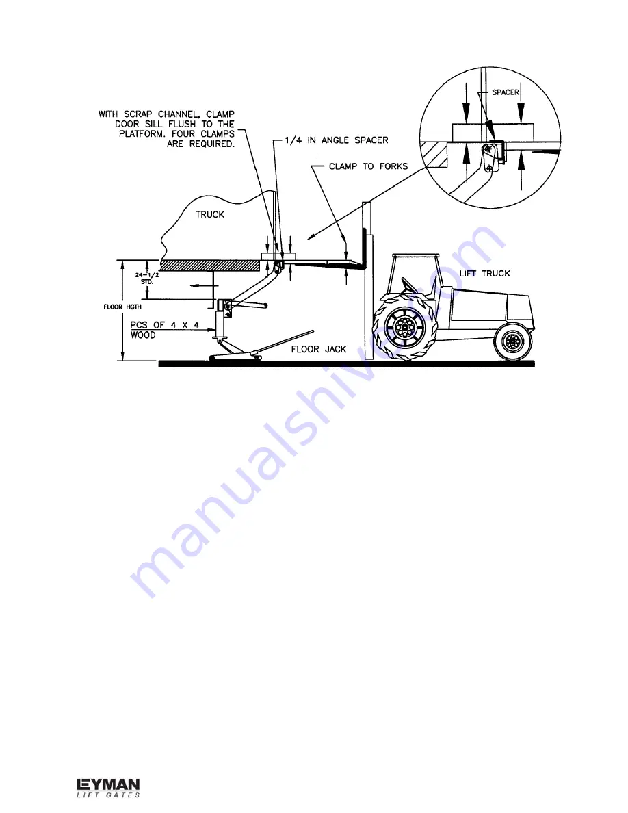
10. Unclamp the four clamps holding the back of the platform next to the door sill.
Caution:
Do not unclamp the tip of the platform.
11. Let the lift truck forks down slowly until they will not go any further. They will stop
about half way down when they meet resistance from the oil in the lift cylinder.
Summary of Contents for TSG Hide-A-Way
Page 5: ...5...
Page 7: ...7 TSG SILL CUTOUT...


