11
12. Install gate control switches in the desired location (refer to wiring on page 14)
and route the wire to the power unit. Slide a piece of supplied shrink tube over
the thermal switch wire and connect the black control wire to thermal switch wire
using the butt connector pre-installed on the wire. Move the shrink tube to cover
the connection and heat to shrink and seal the connection. Connect the white
control wire to the lowering valve in the same manner. Attach the green control
wire with ring terminal to the large open post of the starter solenoid.
13. Use a 12 volt battery for temporary power. Run a wire from the battery to the
starter solenoid. Run a ground wire to the truck.
14. Run the gate up and down to check its operation. If the platform secondary has
a fixed taper instead of a flip ramp, the fixed taper will be off the ground. It
should come within 1” of the ground when the platform is loaded. TSG platforms
are level ride.
15. If the gate operation is correct, finish weld the trunion tube to the mounting
plates and gussets. Also, reinforce chassis channel behind TSG mounting plates
by running two rectangular plates (not supplied) between the chassis channels.
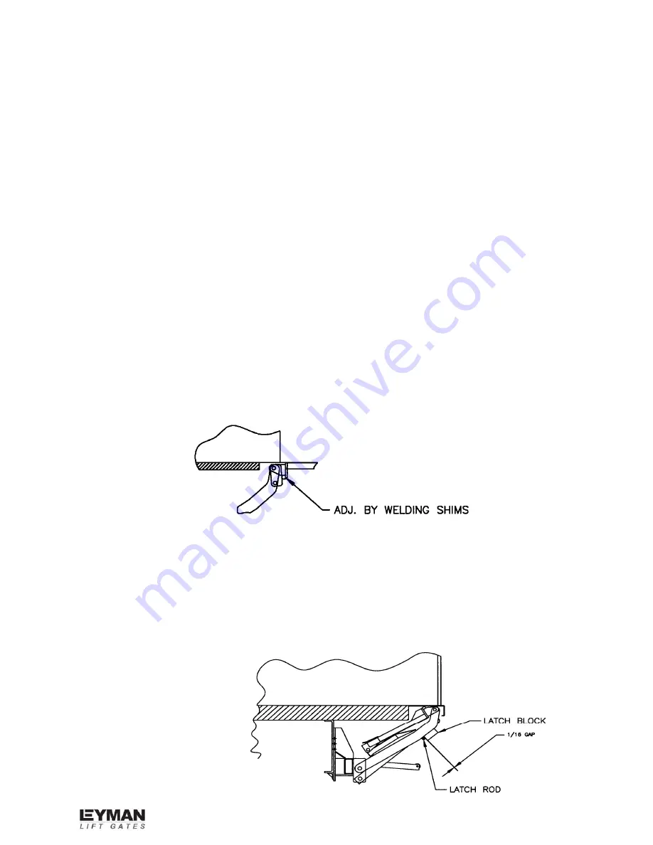
16. Weld shims to stop blocks on platform for proper slope and preload
(approximately 1” high at end of flat on secondary platform). 14 gauge shims
provided in kit will give proper slope (see illustration below). and preload.
View with platform unfolded and in the full up position.
Caution:
Attach ground to stop blocks before welding.
17. Weld on stop block for latch, which holds the gate up in the stored position.
There should be a 1/16” gap between the block and the latch shaft (see
illustration below). This block will hold the gate in the over-the-road position in the
event of hydraulic failure.
Summary of Contents for TSG Hide-A-Way
Page 5: ...5...
Page 7: ...7 TSG SILL CUTOUT...


