


Control panel removal (MX71x)
Warning—Potential Damage:
When replacing the control panel, control panel board, or controller board, replace
only one component at a time. Replace the required component and perform a POR before replacing a second
component. If this procedure is not followed, the printer will be rendered inoperable. Never replace both the control
panel and the controller board without a POR after installing each one or the printer will be rendered inoperable.
Never install or remove these components as a method of troubleshooting while operating in normal user mode.
See
“Controller board/control panel replacement” on page 372
.
Warning—Potential Damage:
When a component has been installed in a machine and has been powered up in
normal user mode, it cannot be used in another machine; it must be returned to the manufacturer. The machine
must be powered up in Diagnostic mode or the controller board, control panel boards, or control panel will become
locked.
1
Remove the toner supply cartridge.
2
Remove the imaging unit.
3
Remove the left cover. See
“Left cover removal (MX71x)” on page 416
.
4
Remove the right cover. See
“Right cover removal (MX71x)” on page 438
.
5
Open the rear door.
6
Remove the upper redrive. See
“Upper redrive removal” on page 571
.
7
Remove the ADF/scanner assembly. See
“ADF/scanner assembly removal” on page 572
.
8
Remove the sensor (standard bin full). See
“Sensor (standard bin full) removal” on page 564
.
9
Remove the standard bin cover. See
“Standard bin cover removal (MX71x)” on page 565
.
10
Raise the control panel to its uppermost position.
11
Remove the control panel left bezel. See the
“Control panel left bezel removal (MX71x)” on page 513
.
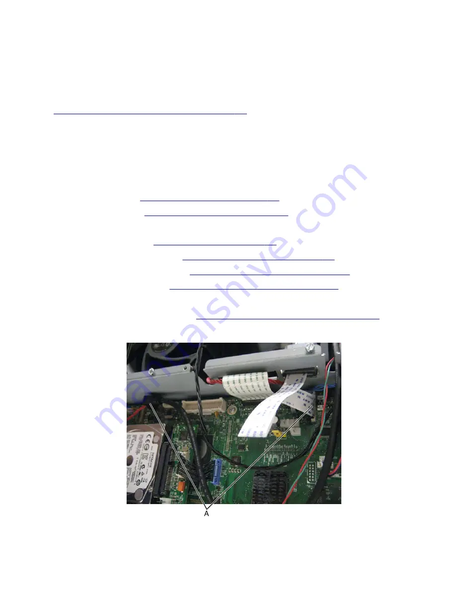
12
Disconnect and remove the two cables (A) from the frame.
Note:
The cables will remain attached to the control panel.
7463
Repair information
488
Summary of Contents for XM5163
Page 111: ...3 Remove the toner supply 4 Remove the imaging unit 7463 Repair information 481...
Page 116: ...15 Disconnect the three cables D 16 Remove the ten inch display 7463 Repair information 486...
Page 122: ...9 Remove the front scanner cover 7463 Repair information 492...
Page 131: ...14 Remove the five screws C 15 Disconnect the five cables D 7463 Repair information 501...
Page 135: ...14 Remove the five screws C 15 Disconnect the five cables D 7463 Repair information 505...
Page 211: ...11 Remove the scanner CCD 7463 Repair information 581...
Page 310: ...4 Remove the other four screws C from the front side of the frame 7463 Repair information 680...
Page 314: ...5 Release the latches A holding the sensor to the media feeder 7463 Repair information 684...
Page 345: ...4 Remove the other four screws C from the front side of the frame 7463 Repair information 715...
Page 349: ...5 Release the latches A holding the sensor to the media feeder 7463 Repair information 719...
Page 357: ...2 Remove the two screws C then remove the left cover 7463 Repair information 727...
Page 413: ...2 Remove the two screws C then remove the right cover 7463 Repair information 783...
Page 431: ...3 Remove the two screws A and then remove the shield 7463 Repair information 801...
Page 433: ...5 Move away the left inner frame to access the parts underneath 7463 Repair information 803...
Page 437: ...5 Move away the left inner frame to access the parts underneath 7463 Repair information 807...
Page 456: ...3 Remove the two screws A and then remove the shield 7463 Repair information 826...
Page 462: ...3 Remove the two screws A and then remove the shield 7463 Repair information 832...
Page 464: ...5 Move away the left inner frame to access the parts underneath 7463 Repair information 834...
Page 466: ...3 Remove the two screws A and then remove the shield 7463 Repair information 836...
Page 510: ...7463 880...


