


User Manual for BPS-4H (High Temp.)
www.levitronix.com
PL-2009-03, Rev04, DCO# 21-101
22
4.1.2 Installation Instructions
!
WARNING
Hazardous voltage may be present.
Always isolate the electrical power supply before making or
changing connections to the unit.
To remove the power, it is recommended to use an over-current
or circuit breaker in close proximity to the controller.
!
WARNING
Hazardous voltage may be present.
The controller housing must be properly grounded. Use one of
the DIN-rail screws on the back side of the controller housing.
!
WARNING
Incorrect mounting of motor connector.
Short circuit possible.
Assure that the “POWER INPUT” connector from the motor is
correctly aligned with the connector of the controller before it is
plugged in (Figure 26). If excessive force is used it is possible to
plug in the connector with the wrong pin alignment, hence
causing short-circuits.
11.
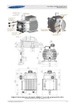
Connect the protective earth wire with a crimp-type end on one of the two DIN-rail screws
(see
Figure 25 / right)
on the backside of the controller (see also protective earth labels on
controller). Use the standard DIN-rail screws already mounted on the clips. Do not use longer
screws as they may generate short-circuit on the PCB.
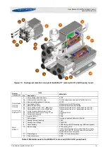
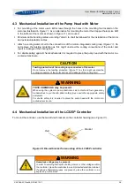
12.
Connect the two motor connectors (sensor and power) to the controller.
Assure that the “POWER
INPUT” connector from the motor is correctly aligned with the connector of the controller before it
is plugged in (
). If excessive force is used it is possible to plug in the connector with the
wrong pin alignment, hence causing short-circuits.
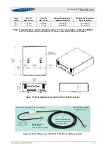
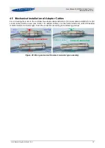
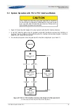
13.
Connect the
PLC-A
module (or user interface
LUI-A
for standalone operation) to the controller (see
Section 4.2.2).
14.
Connect the AC power input connector. Make sure that the polarities are correct
(see
:
•
1 x 230 V (1-phase)
L1 (
L), L2 (
N), PE (= Power Earth)
•
3 x 200 V or 208 V (3-phase)
L1 ,L2, L3, PE (lines can be switched)
(Y-voltage = 115 V or 120 V AC)
•
Minimum Wire Gauge = AWG 18 (Diameter = 1.02 mm)
•
External fuses of 16 A/slow for the LC325P (or equivalent circuit breaker) in all power lines
are recommended (
15.
To secure the connectors, tighten all retaining screws following the torque specifications in